3.5VERIFY OPERATION
PI
SA
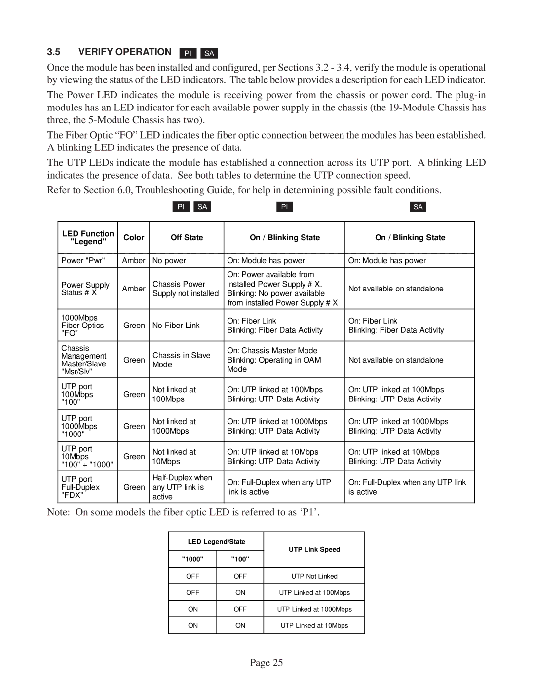
Once the module has been installed and configured, per Sections 3.2 - 3.4, verify the module is operational by viewing the status of the LED indicators. The table below provides a description for each LED indicator.
The Power LED indicates the module is receiving power from the chassis or power cord. The
The Fiber Optic “FO” LED indicates the fiber optic connection between the modules has been established. A blinking LED indicates the presence of data.
The UTP LEDs indicate the module has established a connection across its UTP port. A blinking LED indicates the presence of data. See both tables to determine the UTP connection speed.
Refer to Section 6.0, Troubleshooting Guide, for help in determining possible fault conditions.
PI
SA
PI
SA
LED Function | Color | Off State | On / Blinking State | On / Blinking State | |
"Legend" | |||||
|
|
|
| ||
|
|
|
|
| |
Power "Pwr" | Amber | No power | On: Module has power | On: Module has power | |
|
|
|
|
| |
|
|
| On: Power available from |
| |
Power Supply | Amber | Chassis Power | installed Power Supply # X. | Not available on standalone | |
Status # X |
| Supply not installed | Blinking: No power available |
| |
|
|
| from installed Power Supply # X |
| |
1000Mbps |
|
| On: Fiber Link | On: Fiber Link | |
Fiber Optics | Green | No Fiber Link | |||
Blinking: Fiber Data Activity | Blinking: Fiber Data Activity | ||||
"FO" |
|
| |||
|
|
|
| ||
|
|
|
|
| |
Chassis |
| Chassis in Slave | On: Chassis Master Mode |
| |
Management | Green | Blinking: Operating in OAM | Not available on standalone | ||
Master/Slave | Mode | ||||
"Msr/Slv" |
|
| Mode |
| |
UTP port | Green | Not linked at | On: UTP linked at 100Mbps | On: UTP linked at 100Mbps | |
100Mbps | |||||
"100" |
| 100Mbps | Blinking: UTP Data Activity | Blinking: UTP Data Activity | |
|
|
|
| ||
|
|
|
|
| |
UTP port | Green | Not linked at | On: UTP linked at 1000Mbps | On: UTP linked at 1000Mbps | |
1000Mbps | |||||
"1000" |
| 1000Mbps | Blinking: UTP Data Activity | Blinking: UTP Data Activity | |
|
|
|
| ||
|
|
|
|
| |
UTP port |
| Not linked at | On: UTP linked at 10Mbps | On: UTP linked at 10Mbps | |
10Mbps | Green | ||||
10Mbps | Blinking: UTP Data Activity | Blinking: UTP Data Activity | |||
"100" + "1000" |
|
|
|
| |
UTP port |
| On: | On: | ||
Green | any UTP link is | ||||
link is active | is active | ||||
"FDX" |
| active | |||
|
|
|
Note: On some models the fiber optic LED is referred to as ‘P1’.
LED Legend/State | UTP Link Speed | ||
|
| ||
"1000" | "100" | ||
| |||
|
|
| |
OFF | OFF | UTP Not Linked | |
|
|
| |
OFF | ON | UTP Linked at 100Mbps | |
|
|
| |
ON | OFF | UTP Linked at 1000Mbps | |
|
|
| |
ON | ON | UTP Linked at 10Mbps | |
|
|
| |
Page 25