PI
Module - iConverter GX/TM |
| iConverter, Serial Agent |
| |||||
Identifier - |
|
|
|
|
|
|
|
|
Chassis Number | = | 1 | Switch ON Condition | OFF Condition | H/W | Actual | ||
Slot Number | = | 2 | 1: Fiber Manual | Fiber AN | Off | Off | ||
Model Number | = | 2: UTP Manual | UTP | Off | Off | |||
|
|
| 3: UTP | 10/100 | UTP | 1000 | Off | Off |
Serial Number | = | xxxxxxxx | 4: UTP 10 Mbps | UTP 100 Mbps | Off | Off | ||
Manufacturing Date = | xxxxxxxx | 5: UTP HDX | UTP FDX | Off | Off | |||
Hardware Revision | = | xx | 6: Link Propagate | Link Segment | Off | Off | ||
Software Revision | = | xx | 7: Remote Fault | Normal | Off | Off | ||
|
|
| 8: Symm Fault Det | Normal | Off | Off | ||
LED |
|
| 9: BP A Enabled | BP A Disabled | Off | Off | ||
1: Power | = | On | 10: BP B Enabled | BP B Disabled | Off | Off | ||
2: Power Supply 1 | = | Off | 11: Pause Enabled | Pause Disabled | Off | Off | ||
3: Power Supply 2 | = | On | 12: Slave Only | Master/Slave | Off | Off | ||
4: Power Supply 3 | = | Off | 13: UTP | UTP | Off | Off | ||
5: Fiber Link | = | Off | 14: UTP Crossover | UTP Through | Off | Off | ||
6: BP Master | = | Off | 15: Not Available |
|
|
|
| |
7: UTP 100+10 Link = | Off | 16: Not Available |
|
|
|
| ||
8: UTP 1000+10 Link= | Off | OAM settings: |
|
|
|
| ||
9: UTP FDX | = | Off | 17: IP Protocol State | Off |
|
| ||
|
|
| 18: Management Mode | ah OAM |
|
| ||
Toggle |
| |||||||
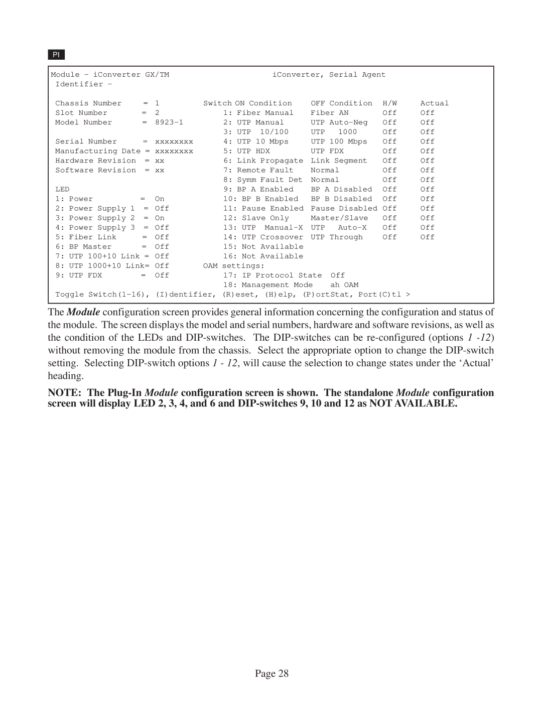
The Module configuration screen provides general information concerning the configuration and status of the module. The screen displays the model and serial numbers, hardware and software revisions, as well as the condition of the LEDs and
NOTE: The
Page 28