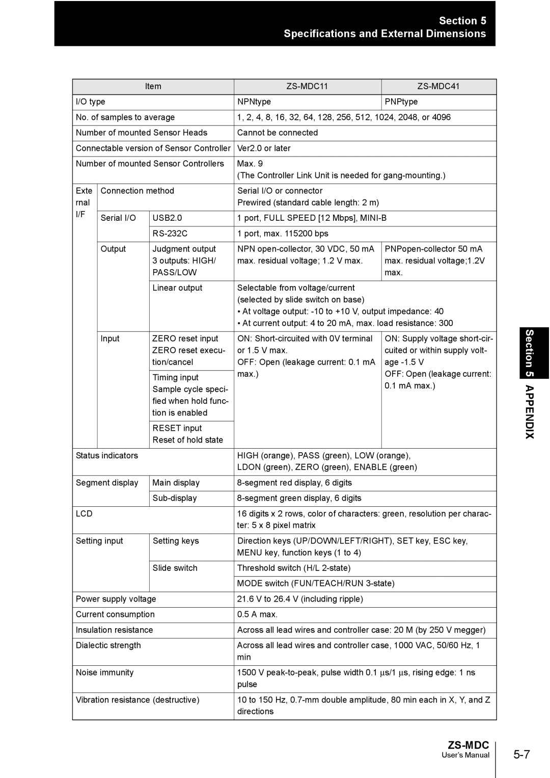
ZS-MDC specifications
The Omron ZS-MDC is a sophisticated multi-functional device designed to enhance the efficiency and reliability of industrial automation systems. Equipped with a variety of features, this device caters to various applications including packaging, assembly, and material handling. Its versatility and advanced technology make it an ideal choice for industries seeking to optimize their operations.One of the main features of the Omron ZS-MDC is its comprehensive sensor integration capability. The device can accommodate multiple sensors and actuators, allowing for flexible configurations tailored to specific applications. This modularity ensures that manufacturers can adapt the device to meet their unique requirements while maintaining high performance.
Another significant feature is the built-in communication interfaces. The ZS-MDC supports various communication protocols like EtherCAT, PROFINET, and Ethernet/IP, which makes it highly compatible with existing automation systems. This ability to seamlessly connect enhances overall system performance and facilitates real-time data exchange, allowing for improved monitoring, control, and diagnostics.
The device is also characterized by its robust design, built to withstand challenging industrial environments. With an IP67 rating, the ZS-MDC is resistant to dust and water, making it suitable for harsh conditions where exposure to contaminants is a concern. Additionally, its durable construction ensures longevity and reduces the need for frequent maintenance, translating to cost savings for manufacturers.
Technologically, the Omron ZS-MDC incorporates advanced processing capabilities enabling it to handle complex tasks with ease. It features high-speed processing and data handling, reducing response times in critical applications. This performance is further enhanced by the integration of intelligent algorithms that enable predictive maintenance and failure detection, ultimately leading to minimized downtime.
User-friendliness is another key characteristic of the ZS-MDC. The device is designed with an intuitive user interface that simplifies configuration and monitoring, thereby reducing the time and expertise required for setup. Moreover, it supports remote access functionality, allowing operators to manage and troubleshoot the device from anywhere, which boosts overall operational efficiency.
In summary, the Omron ZS-MDC stands out with its versatile sensor integration, robust communication capabilities, durable design, advanced processing, and user-friendly interface. These features make it a valuable asset in the realm of industrial automation, helping businesses drive productivity and enhance operational reliability.
