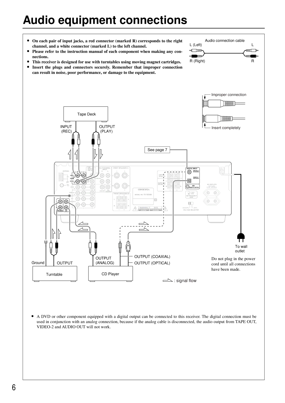
Audio equipment connections
•On each pair of input jacks, a red connector (marked R) corresponds to the right channel, and a white connector (marked L) to the left channel.
•Please refer to the instruction manual of each component when making any con- nections.
•This receiver is designed for use with turntables using moving magnet cartridges.
•Insert the plugs and connectors securely. Remember that improper connection can result in noise, poor performance, or damage to the equipment.
| Tape Deck |
INPUT | OUTPUT |
(REC) | (PLAY) |
See page 7
Audio connection cable |
|
L (Left) | L |
R (Right) | R |
![]() Improper connection
Improper connection
![]() Insert completely
Insert completely
|
| SUB |
| MULTICHANNEL FRONT SPEAKERS A |
| DIGITAL INPUT |
| |||
|
| WOOFER | INPUT |
|
|
| ||||
ANTENNA |
| PRE OUT |
|
|
| DIGITAL 2 |
| |||
| R | L |
|
|
|
| ||||
R | L |
|
|
|
| (COAXIAL) |
| |||
|
|
|
| FRONT |
|
|
|
|
|
|
| (REC) |
|
|
| L | L | CENTER |
|
|
|
AM |
|
|
| SPEAKER |
|
|
| |||
OUT |
|
|
|
|
|
| DIGITAL 1 |
| ||
| TAPE | MONI- |
| SURROUND |
|
|
|
| (OPTICAL) |
|
| (PLAY) | TOR |
|
|
|
| L | L |
|
|
| OUT |
|
|
|
|
|
| |||
| IN |
|
|
|
| SURROUND |
|
|
| |
|
|
|
|
|
|
|
|
| ||
FM |
|
|
|
| R | R | SPEAKERS |
|
| AC OUTLETS |
75 | DVD |
|
|
| R | R |
| SWITCHED | ||
|
|
|
|
|
|
|
| REMOTE CONTROL | TOTAL 100W MAX. | |
| IN |
|
|
|
|
|
|
|
|
|
|
|
|
| CENTER | SUB |
|
|
|
|
|
|
|
|
| WOOFER |
|
|
|
|
| |
|
|
|
|
|
|
| 10kHz |
| ||
|
|
|
| FRONT SPEAKERS B |
|
|
| |||
| IN |
|
|
| MODEL NO. |
| 9kHz |
| ||
GND |
|
|
|
|
| AM FREQUENCY |
| |||
|
|
|
|
|
|
|
| |||
| OUT |
|
|
|
|
|
|
| STEP |
|
|
|
|
| L | L |
|
|
|
| |
|
|
|
|
|
|
|
|
| ||
L |
|
|
|
|
|
|
|
|
| |
| IN |
|
|
| R | R |
|
|
|
|
R |
|
|
|
|
|
|
|
| ||
R | L | V |
|
|
|
| 120V |
| ||
PHONO CD |
|
|
|
|
|
|
| VOLTAGE SELECTOR |
| |
|
|
|
|
|
|
|
|
|
| |
Ground
| OUTPUT |
|
|
|
| OUTPUT (COAXIAL) |
|
|
|
|
| ||
|
|
|
|
| ||
|
|
|
|
| ||
|
|
|
|
|
| |
OUTPUT | (ANALOG) |
|
|
|
| OUTPUT (OPTICAL) |
Turntable | CD Player |
|
|
|
| |
 : signal flow
To wall outlet
Do not plug in the power cord until all connections have been made.
•A DVD or other component equipped with a digital output can be connected to this receiver. The digital connection must be used in conjunction with an analog connection, because if the analog cable is disconnected, the audio output from TAPE OUT,
6