Identification of Controls (continued)
Main Unit
ANTENNA INPUT ![]()
![]()
HEADPHONE JACK
AV INPUT/
AUDIO R AUDIO L/MONO VIDEO
SCART1 INTERFACE
SCART2 INTERFACE
AUDIO
DVI IN
AUDIO
Y
Cb/Pb
Cr/Pr
COMPONENT IN
AUDIO R
AUDIO L/MONO
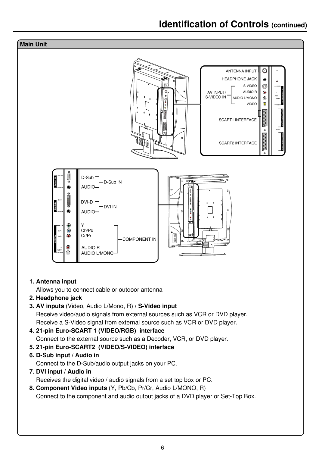
1.Antenna input
Allows you to connect cable or outdoor antenna
2.Headphone jack
3.AV inputs (Video, Audio L/Mono, R) /
Receive video/audio signals from external sources such as VCR or DVD player. Receive a
4.21-pin Euro-SCART 1 (VIDEO/RGB) interface
Connect to the external source such as a Decoder, VCR, or DVD player.
5.21-pin Euro-SCART2 (VIDEO/S-VIDEO) interface
6.D-Sub input / Audio in
Connect to the
7.DVI input / Audio in
Receives the digital video / audio signals from a set top box or PC.
8.Component Video inputs (Y, Pb/Cb, Pr/Cr, Audio L/MONO, R)
Connect to the component and audio output jacks of a DVD player or
6
