Setup menus
USER menu
<TIME CODE> (continued)
| Item |
| Setting |
| ||||
|
|
|
|
|
|
|
| Description |
No. | Superimposed | No. |
| Superimposed | ||||
display |
| display |
| |||||
|
|
|
| |||||
|
|
|
|
|
|
|
|
|
|
|
|
|
|
|
|
|
|
509 | DF MODE | 0000 |
|
|
| DF | This selects the DF/NDF mode for CTL and TCG. | |
|
| 0001 |
|
|
| NDF |
| 0: Drop frame mode. |
|
|
|
|
|
|
|
| 1: |
|
|
|
|
|
|
|
| <Note> |
|
|
|
|
|
|
|
| No. 509 is valid when the CONTROL is LOCAL or LOCAL |
|
|
|
|
|
|
|
| ENA of item 004 to “ENA”. |
|
|
|
|
|
|
|
| |
510 | RUN MODE | 0000 |
|
|
| REC |
| This selects the time code generator run mode. |
|
| 0001 |
|
|
| FREE | 0: Generator runs only during recording. | |
|
|
|
|
|
|
|
| 1: Generator runs during usual operation. |
|
|
|
|
|
|
|
| <Note> |
|
|
|
|
|
|
|
| Even if “0” is selected, the time code generator runs during |
|
|
|
|
|
|
|
| usual operation when “1” is selected at the setting menu |
|
|
|
|
|
|
|
| No. 504 (REGEN MODE). |
|
|
|
|
|
|
| ||
511 | TC OUT | 0000 |
|
| V OUT | This is used to switch the phase of the time code, which is | ||
| REF | 0001 |
|
|
| TC_IN | output from the TIME CODE OUT connector, for the external | |
|
|
|
|
|
|
|
| LTC input when the TC INT/EXT switch is at the EXT position. |
|
|
|
|
|
|
|
| (In EE mode only) |
|
|
|
|
|
|
|
| 0: Time code is synchronized with output video signal. |
|
|
|
|
|
|
|
| 1: Time code is synchronized with external time code input. |
|
|
|
|
|
|
|
| |
512 | VITC OUT | 0000 |
|
|
| SBC |
| For selecting the method used to output the VITC which is to |
|
| 0001 |
|
|
| VAUX | be superimposed onto the output video signal. | |
|
|
|
|
|
|
|
| 0: During recording: |
|
|
|
|
|
|
|
| The input time code, which was selected using the setup |
|
|
|
|
|
|
|
| menu item No. 505 (EXT TC SEL) setting and TC IN/EXT |
|
|
|
|
|
|
|
| switch, is output as the VITC. |
|
|
|
|
|
|
|
| During playback: |
|
|
|
|
|
|
|
| The time code recorded in the SBC area is output as the |
|
|
|
|
|
|
|
| VITC. |
|
|
|
|
|
|
|
| 1: During recording: |
|
|
|
|
|
|
|
| The time code detected from the input video signals is |
|
|
|
|
|
|
|
| output as the VITC. |
|
|
|
|
|
|
|
| During playback: |
|
|
|
|
|
|
|
| The time code recorded in the VAUX area is output as the |
|
|
|
|
|
|
|
| VITC. |
|
|
|
|
|
|
|
| <Note> |
|
|
|
|
|
|
|
| When video signals are recorded, the time code detected from |
|
|
|
|
|
|
|
| the input video signals is automatically recorded in the VAUX |
|
|
|
|
|
|
|
| area. |
|
|
|
|
|
|
|
|
|
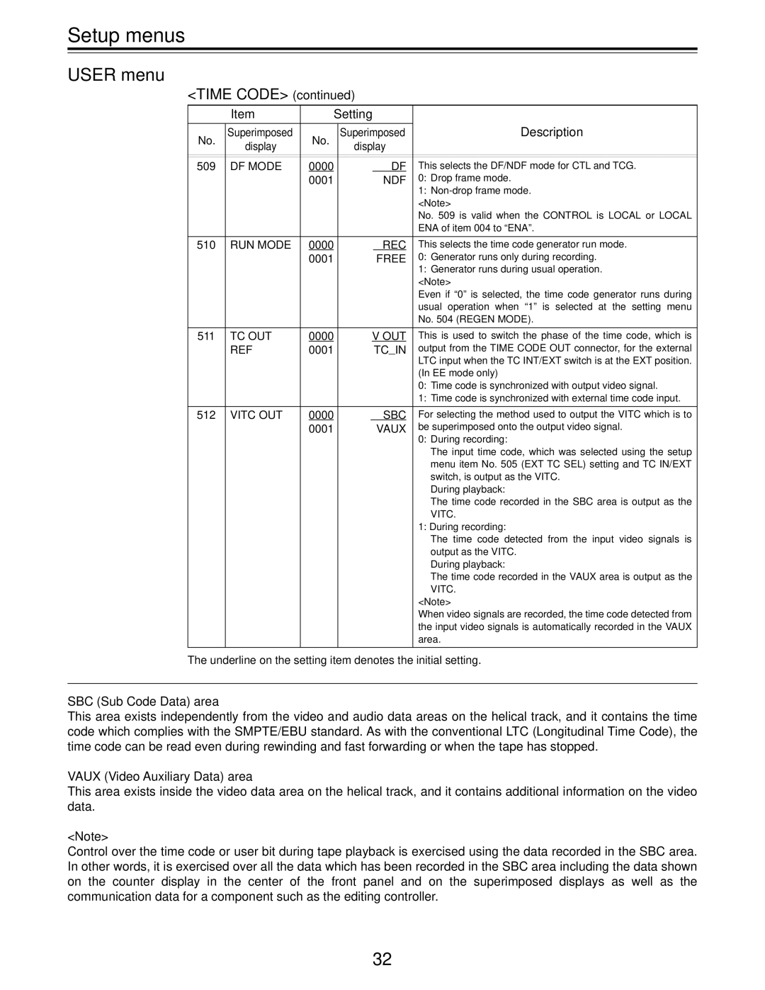
The underline on the setting item denotes the initial setting.
SBC (Sub Code Data) area
This area exists independently from the video and audio data areas on the helical track, and it contains the time code which complies with the SMPTE/EBU standard. As with the conventional LTC (Longitudinal Time Code), the time code can be read even during rewinding and fast forwarding or when the tape has stopped.
VAUX (Video Auxiliary Data) area
This area exists inside the video data area on the helical track, and it contains additional information on the video data.
<Note>
Control over the time code or user bit during tape playback is exercised using the data recorded in the SBC area. In other words, it is exercised over all the data which has been recorded in the SBC area including the data shown on the counter display in the center of the front panel and on the superimposed displays as well as the communication data for a component such as the editing controller.
32
