Parts and their functions
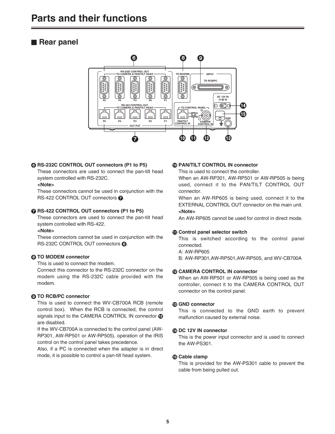
$ Rear panel
6
![]() TO CAMERA & PAN/TILT HEAD
TO CAMERA & PAN/TILT HEAD ![]()
P5 |
|
| P4 | P3 | P2 | P1 | |||
|
|
|
|
|
|
|
| ||
|
|
|
| TO CAMERA & PAN/TILT HEAD |
|
| |||
P5 |
|
| P4 | P3 | P2 | P1 | |||
|
|
|
|
| OUT PUT |
|
|
| |
|
|
|
|
|
|
|
| ||
|
|
|
|
|
|
|
|
|
|
|
|
|
|
|
|
|
|
|
|
|
|
|
|
|
|
|
|
|
|
7
6
<Note>
These connectors cannot be used in conjunction with the
7RS-422 CONTROL OUT connectors (P1 to P5)
These connectors are used to connect the
<Note>
These connectors cannot be used in conjunction with the
8TO MODEM connector
This is used to connect the modem.
Connect this connector to the
9TO RCB/PC connector
This is used to connect the
If the
Also, if a PC is connected when the adapter is in direct mode, it is possible to control a
89
TO MODEM |
| INPUT |
|
|
| TO RCB/PC |
|
|
| DC 12V IN |
|
TO CONTROL PANEL | > | ||
| A |
| ? |
|
|
| |
| B | GND |
|
|
|
| |
PAN/TILT |
| CAMERA |
|
CONTROL IN |
| CONTROL IN |
|
:; < =
:PAN/TILT CONTROL IN connector This is used to connect the controller.
When an
When an
<Note>
An
;Control panel selector switch
This is switched according to the control panel connected.
A:
B:
<CAMERA CONTROL IN connector
When an
=GND connector
This is connected to the GND earth to prevent malfunction caused by external noise.
>DC 12V IN connector
This is the power input connector and is used to connect the
?Cable clamp
This is provided for the
5