7.Using the UPS monitoring software and contact signal
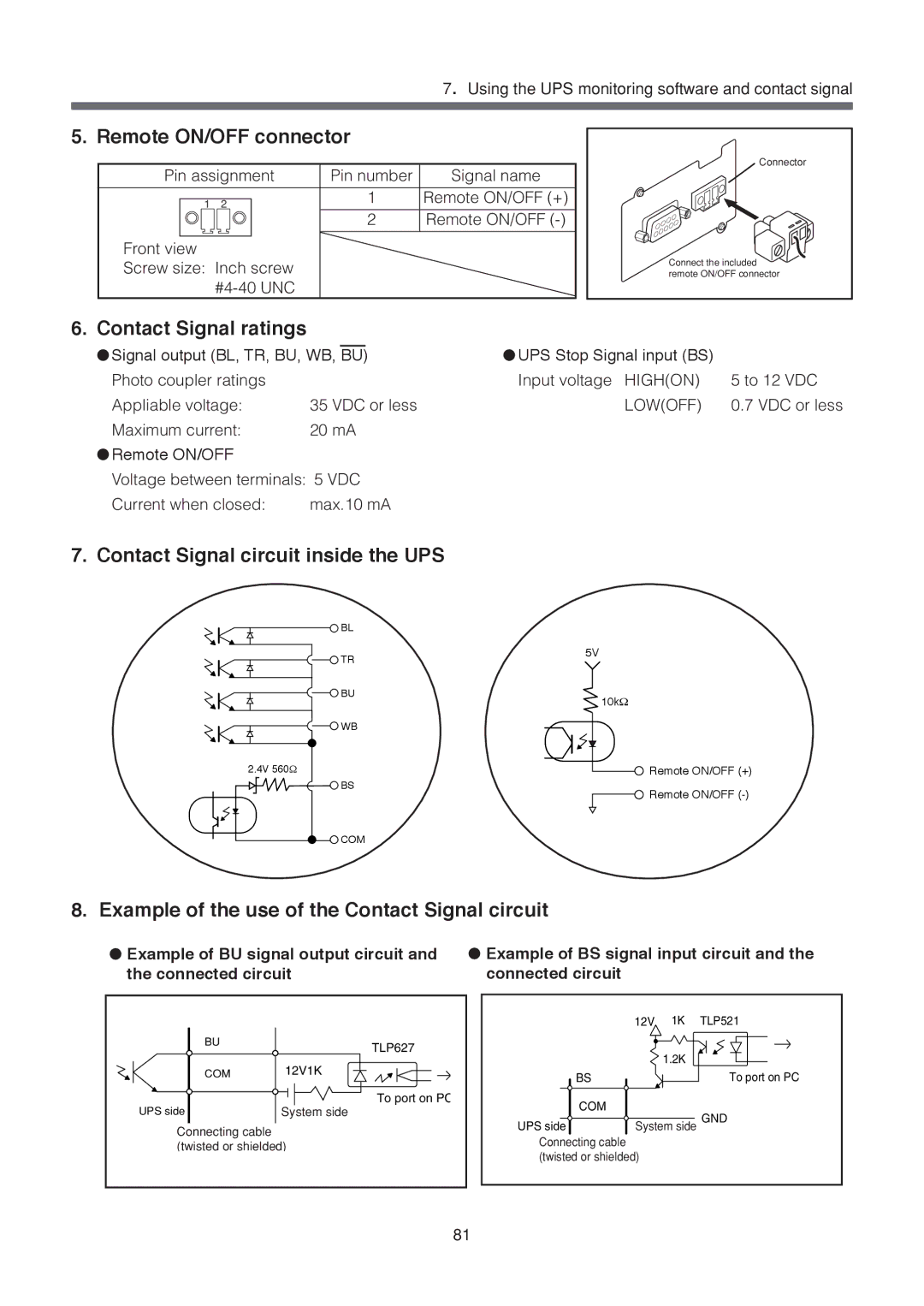
5. Remote ON/OFF connector
Pin assignment |
| Pin number | Signal name | ||||||
|
|
|
|
|
|
|
|
|
|
|
|
|
|
|
|
| 1 | Remote ON/OFF (+) | |
| 1 | 2 |
|
| |||||
|
|
|
|
|
|
|
| 2 | Remote ON/OFF |
|
|
|
|
|
|
|
|
|
|
|
|
|
|
|
|
|
|
|
|
Front view |
|
|
|
|
|
|
| ||
Screw size: Inch screw |
|
|
| ||||||
|
|
|
|
|
| ||||
Connector
Connect the included remote ON/OFF connector
6. Contact Signal ratings
|
|
|
|
|
|
● Signal output (BL, TR, BU, WB, BU) | ● UPS Stop Signal input (BS) |
| |||
Photo coupler ratings |
|
|
| Input voltage HIGH(ON) | 5 to 12 VDC |
Appliable voltage: | 35 VDC or less | LOW(OFF) | 0.7 VDC or less | ||
Maximum current: | 20 mA |
|
| ||
● Remote ON/OFF |
|
|
|
|
|
Voltage between terminals: 5 VDC |
|
| |||
Current when closed: | max.10 mA |
|
| ||
7. Contact Signal circuit inside the UPS
![]() BL
BL
| TR | 5V |
|
| |
| BU | 10kΩ |
|
| |
| WB |
|
2.4V 560Ω |
| Remote ON/OFF (+) |
| BS | Remote ON/OFF |
|
| |
| COM |
|
8. Example of the use of the Contact Signal circuit
●Example of BU signal output circuit and the connected circuit
●Example of BS signal input circuit and the connected circuit
BU | TLP627 |
| |
COM | 12V1K |
| To port on PC |
UPS side | System side |
Connecting cable |
|
(twisted or shielded) | |
| 81 |
| 12V | 1K | TLP521 |
|
| 1.2K |
|
BS |
|
| To port on PC |
COM | System side GND | ||
UPS side | |||
Connecting cable |
|
|
|
(twisted or shielded) |
|
| |