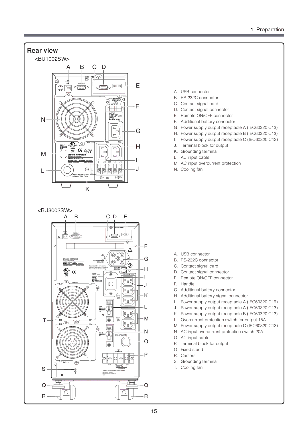
Rear view
<BU1002SW> |
|
|
|
|
A | B | C | D |
|
|
|
|
| E |
|
|
|
| F |
N |
|
|
|
|
|
|
|
| G |
|
|
|
| H |
M |
|
|
| I |
|
|
|
| |
L |
|
|
| J |
|
|
|
| |
|
| K |
|
|
<BU3002SW> |
|
|
|
|
A | B |
| C D | E |
|
|
|
| F |
|
|
|
| G |
| See installation Instructions | H |
| before connecting to the supply. | |
| Not For Current Interrupting. | |
| MAX | I |
|
| J |
|
| K |
|
| L |
T |
| M |
|
| |
| INPUT | N |
| 50/60Hz 16A 1ø3W |
|
|
| O |
|
| P |
S | Refer to the instruction manual for the |
|
| tightening torque. |
|
| Use Copper Conductor |
|
| Only. |
|
Q |
| Q |
R |
| R |
1. Preparation
A.USB connector
B.
C.Contact signal card
D.Contact signal connector
E.Remote ON/OFF connector
F.Additional battery connector
G.Power supply output receptacle A (IEC60320 C13)
H.Power supply output receptacle B (IEC60320 C13)
I.Power supply output receptacle C (IEC60320 C13)
J.Terminal block for output
K.Grounding terminal
L.AC input cable
M.AC input overcurrent protection
N.Cooling fan
A.USB connector
B.
C.Contact signal card
D.Contact signal connector
E.Remote ON/OFF connector
F.Handle
G.Additional battery connector
H.Additional battery signal connector
I.Power supply output receptacle A (IEC60320 C19)
J.Power supply output receptacle A (IEC60320 C13)
K.Power supply output receptacle B (IEC60320 C13)
L.Overcurrent protection switch for output 15A
M.Power supply output receptacle C (IEC60320 C13)
N.AC input overcurrent protection switch 20A
O.AC input cable
P.Terminal block for output
Q.Fixed stand
R.Casters
S.Grounding terminal
T.Cooling fan
15