Manuals
/
Omron
/
Computer Equipment
/
Power Supply
Omron
BU3002SW, BU1002SW
specifications
Side view
Models:
BU3002SW
BU1002SW
1
16
93
93
Download
93 pages
54.62 Kb
13
14
15
16
17
18
19
20
Troubleshooting
Specs
Install
Circuit block diagram
Contact signal
Connecting the equipment
Dimension
Maintenance
Perform UPS service setup
Connector
Page 16
Image 16
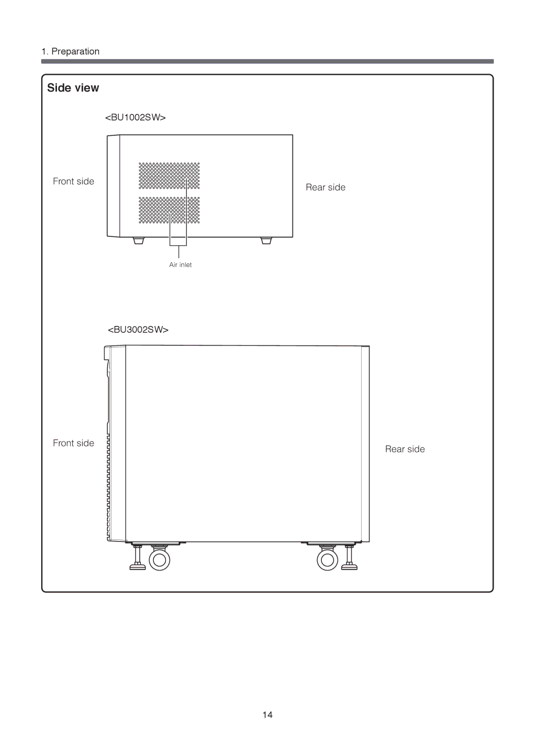
1. Preparation
Side view
<BU1002SW>
Front side
Rear side
Air inlet
<BU3002SW>
Front side
Rear side
14
Page 15
Page 17
Page 16
Image 16
Page 15
Page 17
Contents
BU1002SW/BU3002SW
Introduction
Internal Battery
Procedure from installation to operation
Start Installation/connection
Table of Contents
Keep plastic package bags out of reach of children
Safety precautions
Misuse may cause death or serious injury
Do not disassemble, repair, or modify the unit
Provide secure grounding
Do not pinch or tie the cable of the unit
Doing so may compromise the safety of devices
Do not allow the unit to come in contact with water
If fluid leaks from the unit, do not touch the fluid
Do not insert metal objects into the battery connectors
Perform replacement on a stable and flat place
Use a specified battery for replacement
Do not disassemble or modify the battery
Do not put the battery into fire and do not break it
Do not use a new battery and an old battery at the same time
Do not perform a withstand voltage test
Quitting Battery Mode
Rebooting
Scheduled operation using the UPS monitoring software
This unit uses lead acid batteries
Preparation
2Checking the contents
Unpacking the product
Name of each part
Front view
Side view
Rear view
BU1002SW BU3002SW
Explanation of symbols used on unit
Installation and connection
Precautions and notes on installation and connection
Do not install the unit in other than specified orientations
Installation and connection
Do not perform a withstand voltage test
Installation and connection
BU1002SW
BU3002SW
Casters locked
Connecting the equipment
Group control of power supply output
Connecting a device to the power supply output BU1002SW
Output on Output OFF
Nfpa
Input plug L6-15P Front view
Connecting a device to the power supply output BU3002SW
BU3002SW Rated value of output capacity Max kVA/2100W
Rear panel
Input plug L6-20P Front view
Checking the operation
Turn on the units power switch
Bring all the connected devices into operation
Battery Mode, check the units LED display and beep sound
OFF
Measuring the initial value of backup time
Charging the battery
Recharging the battery
Precautions and notes for operation
Operation
Explanation
Start procedure
Start and stop procedures and basic operation
Operation Turn on the power switch of the UPS
Operation after a power failure
Setting switch 1 can be used to turn the beeper ON/OFF.
Stop procedure
Operation during recovery from a power failure
Connection capacity/battery level meter
Interpreting beeps and displays
Displays and beeps in normal operation
Display and beep for battery replacement
Suspending a beep
UPS functions
Self-diagnosis test
Description of the auto battery test function
Changing the setting of the functions
Setting switch function list
UPS functions
BS signal reception time corresponds to the setting switch
BS signal valid range setting setting switch
Settings available for this operation are shown below
UPS operation mode settings
Settable items and explanations
OFF
Settings
Cold start
Measuring the backup time
How to measure backup time
Estimated backup time
For Windows Server 2003/XP/Me/2000/Windows NT/Linux/Mac
BUM100S
Maintenance and Inspection
Checking the battery
Life of battery estimated replacement timing
Methods for checking the battery
Replacing the battery
Battery recycling
Procedure for recycling the battery
Do not hold the connector or cable of the battery pack
Tighten the 2 screws
Battery replacement is now complete
Red tape
Tighten 2 screws
After replacing the battery during operation
Replacing the fan
Do not put your fingers into the fan
Fan replacement procedure
Cleaning
Cleaning the UPS
Using the UPS monitoring software and contact signal
UPS monitoring software
Software title
Connect the UPS to a computer
RS-232C
When using UPS Power Manager UPS monitoring software for Mac
When connecting 2 or more computers to the UPS
Explanation
Install the included UPS service driver on the computer
Connector
Perform UPS service setup
Click
Recycling and Discarding the Battery
Stopping the UPS
How to set up UPS service set the time to shut down Windows
Check Set Click
Check Set
Check Set
Contact signal
Contact Signal
Signal output
Low battery level signal output BL
Items that can be set using the contact signal card
Remote ON/OFF Signal
Output delay time setting for backup signal output BU
BU/BL signal reverse output setting
Insert/ removal method of contact signal card
Contact Signal Connector female DSUB9P
Remote ON/OFF connector
Contact Signal ratings
Contact Signal circuit inside the UPS
Example of the use of the Contact Signal circuit
Precautions and notes for the use of the Contact Signal
Remote ON/OFF circuit
Using an SNMP/Web card
Adding an SNMP/Web card
Specifications
Description features
SNMP/Web card outline
Extending the backup time
Connecting an additional battery unit
Adding BUM300S to the BU3002SW
Troubleshooting
Problem Check and remedy
Specifications
References
Dimensions
BU3002SW
Circuit block diagram
Related products
K1L-D-06051B
Top
Page
Image
Contents