Convertible Camera Model No. AW-E800
Lightning flash with arrowhead sym
Contents
Preface
Features
Special Notes on Operation
Donts
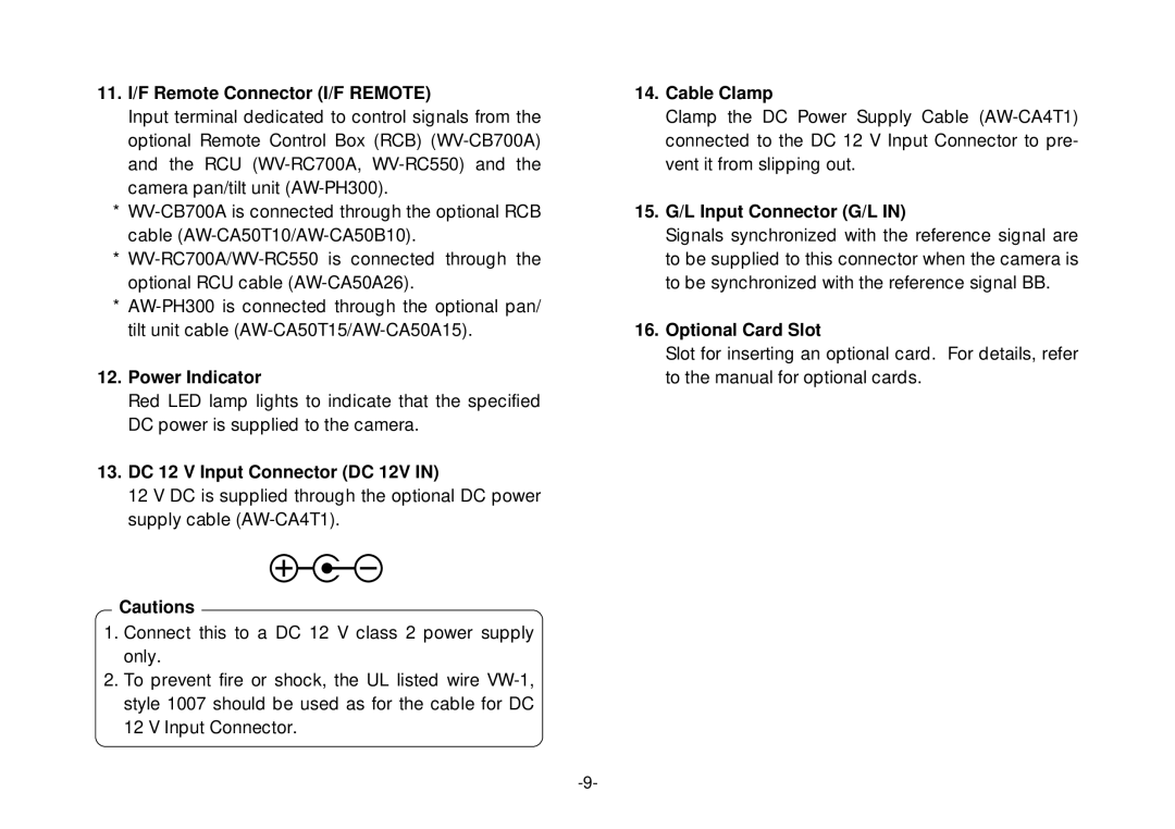
Precautions
DOS
Major Operating Controls and Their Functions
Cooling Fan
Menu Switch MENU/M
ITEM/AWC Switch ITEM/AWC
Lens fixing ring knob
Iris Connector Iris
YES/ABC Switch YES/ABC/+
NO/BAR Switch NO/BAR/−
Video Output Connector Video OUT
15. G/L Input Connector G/L
11. I/F Remote Connector I/F Remote
Power Indicator
DC 12 V Input Connector DC 12V
Lens Mounting
Mounting
Camera Mounting
Flange Back Adjustment for Zoom Lens
Iris Gain Control in a Lens
Automatic iris power zoom lens
Connections
Connection of Device with a Composite Input Connector
WV-RC700A
Connection of a Remote Control Unit RCU
Connection of a Remote Control BOX RCB
Lens
Connection of Devices with Camera PAN/TILT Control System
Signal BB
Connection with Multiple Cameras Color Lock Mode
Connection of Computer
Color temperature and adjustment of white balance
Adjustment
Camera
Automatic White Balance Control AWC
Automatic Tracking White Balance Setting ATW
Manual White Balance Setting
Black Balance Adjustment
Reset to 3 200K or 5 600K White Balance
Total Pedestal Level ADJUST- Ment
Horizontal Phase Control
GEN-LOCK Adjustment
Color Phase Adjustment
Setting by Camera
USE Mode Setting
Camera RCU RCB
Setting by RCU RCB or Hybrid Control Panel
Main Menu Screen
Menu Item Setting
Menu Item Setting
Main Menu of User Mode
From RCU RCB
Setting
From the camera alone
SUB Menu Halogen Mode, Fluorescent Mode, Outdoor Mode
Auto ND ELC Setting Auto ND ELC ON/OFF
Video Level Adjustment Picture Level -50 +50
Detecting Ratio Adjustment Light PEAK/AVG P50 A50
Manual Gain Up Control Setting Manu Gain Up DB 30 dB / N/Eye
0Skin Color Adjustment Flesh Tone -3 +3
Black Level Setting Pedestal -30 +30
Contrast Adjustment Contrast Gamma LOW/MID/HIGH
Chroma Level Adjustment Chroma Level -3 +3
7Detail Select Setting DTL Select Normal/Super
4Sub Carrier Phase Coarse Adjustment SC Coarse 1/2/3/4
5Subcarrier Phase Fine Adjustment SC Fine -511 +511
6Color Bar Setup Setting Color Bar Set 0.0 IRE/7.5 IRE
Page
@5Negative/Positive Selection Nega/Posi Posi/Nega
@3CCD Read Out Mode Setting V Resolution Normal/Fine
Sub Menu User Mode
#1Auto Iris Level Fine Adjustment Auto Iris Adjust ON/OFF
@8Video Level Adjustment Picture Level -50 +50
@9Detecting Ratio Adjustment Light PEAK/AVG P50 A50
100, 1/250, 1/500, 1/1 000, 1/2 000, 1/4
#3Electronic Shutter Step Setting Step OFF/1/100 1/10
#6Gain Up Setting Gain AGC HIGH/AGC LOW/ 0 dB 30 dB / N/Eye
#5CCD Read Out Mode Setting Field/Frame Field/Frame 1/Frame
Pedestal, B Pedestal
#7Black Level Setting Pedestal -30 +30
#8Chroma Level Adjustment Chroma Level -3 +3
$0Highlight Chroma Setting Highlight Chroma
$5Subcarrier Phase Fine Adjustment SC Fine -511 +511
$22-dimensional Lowpass Filter Setting 2D LPF
$3Horizontal Phase Adjustment H Phase -206 +49
$4Subcarrier Phase Coarse Adjustment SC Coarse 1/2/3/4
5Corner Detail Setting Corner Detail OFF/ON
0Noise Suppress Compensation Level Setting Noise Suppress 1
2Dark Detail Compensation Level Setting Dark Detail 0
3Chroma Detail Compensation Level Setting Chroma Detail 0
1Flare Correction Level Setting Flare R/G/B 0
8Gamma Correction Level Setting Gamma 0.35
9Knee Compensation Level Setting Knee Point 88% 98%/Dynamic
0White Clip Level Setting White Clip 95% 110%
Setting to initial set
Setting to Initial SET
Initial Settings of the Setting Items Factory preset values
User Mode
Wide
Appearance
Ntsc
Specifications
Back Panel MENU, ITEM/AWC, YES/ABC, NO/BAR
Optional Accessories
Standard Accessories
NM1199-1010 7J1A402B