Model No. CF-74JCJBDxM
For U.K
Laser Safety Information
Safety Precautions
Precautions Battery Pack
Contents
Specifications
Main Specifications
Wireless LAN
Names and Functions of Parts
Right side
Block Diagram
Page
Troubleshooting
Power-On Self Test Boot Check
Stuck key
02D0 System cache error Cache disabled
Self Diagnosis Test
Operation of PC-Diagnostic Utility
Selection of tested device
To skip Bios password
Wiring Connection Diagram
Removing the HDD
Battery Pack
Preparation
HDD Unit
Removing the Dimm Memory Card
Removing the Handle Assy
Removing the Bottom Case
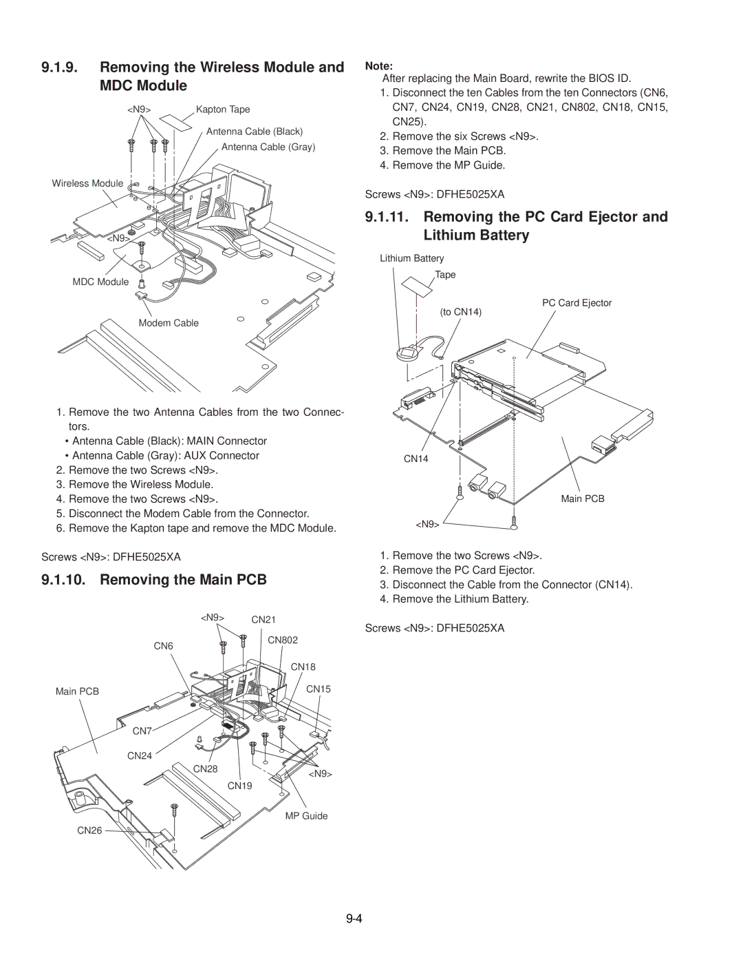
Removing the Wireless Module and MDC Module
PCB
Removing the Display unit
Preparation
Removing the Touch PAD and PAD PCB
Removing the Finger PCB
Reassembly Instructions
Arranging the W-LAN L and R Cable
Attaching the LCD Damper C and LCD Damper D
Arranging the LCD/TS Cable
Attaching the Cloth
Arranging the TP Power Cable and Attaching the TP/LCD Sheet
Setting the Inverter and Arranging the Inverter Cable
LCD Unit
Fixing of the LCD Front Cabinet
Setting the LCD Front Cabinet
Setting the Display unit
Setting the USB PCB
Arranging the USB Cable
Setting the BT PCB
Setting the SD PCB, Heat Sink FAN Motor
Applying Grease on the Heat Sink
Setting the DC-IN PCB and I/O PCB
Arranging the DC-IN Cable
Setting the PC Card Ejector and Lithium Battery
Arranging the Lithium Battery
Arranging the FAN Cable
Setting the Wireless Module and MDC Module
Arranging the Modem Cable
Setting the Bottom Case
Setting the Handle Assy
Setting the Speaker and the LED PCB
Soldering the Speaker Cable and Setting the Speaker Rubber
Setting the Keyboard
Center Cover
Setting the Dimm Memory Card and Dimm Cover
Setting the HDD
Latch HDD Unit Battery Pack DVD-ROM Drive Unit
Exploded View
Screw tightening torque
Screw tightening torque
CF-74JCJBDxM
Replacement Parts List
Accessories
NRP
DFHR6204ZA MODELAN-2
DFHE0277ZA Gasket
QTY
EEFCX0D221R
EEFCX0D331R
EEFCX0G151R
EEFUD0J151ER
EEFSX0D331ER
EEFCX0J101R
CONNECTOR, USB
Connector
CONNECTOR, Dimm
Thermistor
Power Management Swtich
Gigabit LAN Switch
IC, FET Switch
IC, Audio Power Amplifier
Common Mode Filter Array
DC Power Line Inductor
DC Power Line Beads
DC/DC Controller for CPU
TRANSISTOR, FET
B1GBCFNN0042 Transistor
FET
ERJ2GEJ102X RESISTOR, 1/16W, 1KO
ERJ2RKF49R9X
ERJ2RKF80R6X
ERJ2RKF2371X
ERJ2RKF1002X RESISTOR, 1/16W, 10KO
ERJ2RKF4530X
ERJ2GEJ511X
ERJ2RKF3241X
ERJ2GEJ150X
ERJ2GEJ474X
ERJ2RKF2002X RESISTOR, 1/16W, 20KO
ERJ2GEJ272X
ERJ2RHD303X RESISTOR, 1/16W, 30KO
ERJ2GEJ221X
ERJ2RKF3161X
ERJ2RKF2402X RESISTOR, 1/16W, 24KO
ERJ2RKF1003X
EVQPLDA15 Switch
Jack
DEARA8AJ473M Resistor Array
IC, Touchpanel Controller
ERJ2GEJ822X
ERJ2GEJ152X
Inductor B1GBCFNN0042 Transistor
Bluetooth Module
Incuctor
Transistor ERJ2GEJ103X RESISTOR, 1/16W, 10KO