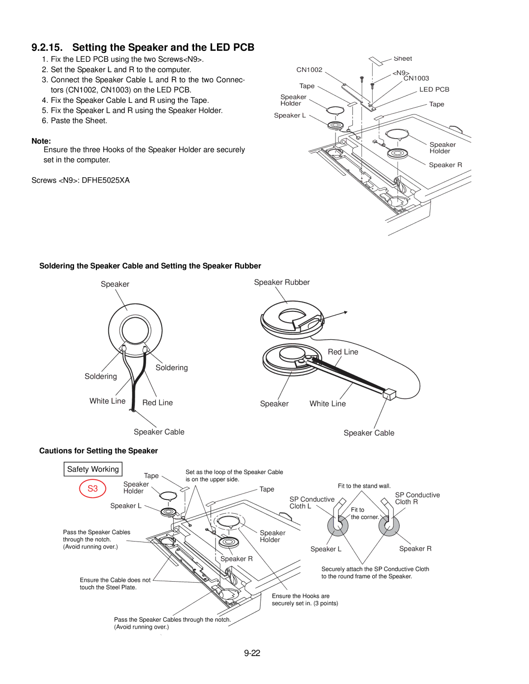
9.2.15. Setting the Speaker and the LED PCB
1.Fix the LED PCB using the two Screws<N9>.
2.Set the Speaker L and R to the computer.
3.Connect the Speaker Cable L and R to the two Connec- tors (CN1002, CN1003) on the LED PCB.
4.Fix the Speaker Cable L and R using the Tape.
5.Fix the Speaker L and R using the Speaker Holder.
6.Paste the Sheet.
Note:
Ensure the three Hooks of the Speaker Holder are securely set in the computer.
Screws <N9>: DFHE5025XA
Soldering the Speaker Cable and Setting the Speaker Rubber
| Sheet | |
CN1002 | <N9> | |
| ||
Tape | CN1003 | |
LED PCB | ||
Speaker | ||
| ||
Holder | Tape | |
Speaker L |
| |
| Speaker | |
| Holder | |
| Speaker R |
Speaker | Speaker Rubber |
Red Line
Soldering
Soldering
White Line | Red Line |
Speaker Cable
Cautions for Setting the Speaker
Safety Working
Tape
S3 Speaker
Holder
Speaker L
Speaker | White Line |
Speaker Cable
Set as the loop of the Speaker Cable is on the upper side.
Tape |
| Fit to the stand wall. |
| SP Conductive | |
| SP Conductive | |
| Cloth R | |
| Cloth L | |
| Fit to | |
|
| |
|
| the corner. |
Pass the Speaker Cables | Speaker |
|
through the notch. | Holder |
|
(Avoid running over.) | Speaker L | Speaker R |
Speaker R
Ensure the Cable does not ![]()
![]() touch the Steel Plate.
touch the Steel Plate.
Securely attach the SP Conductive Cloth to the round frame of the Speaker.
Ensure the Hooks are securely set in. (3 points)
Pass the Speaker Cables through the notch. (Avoid running over.)