9.2.6.Setting the USB PCB
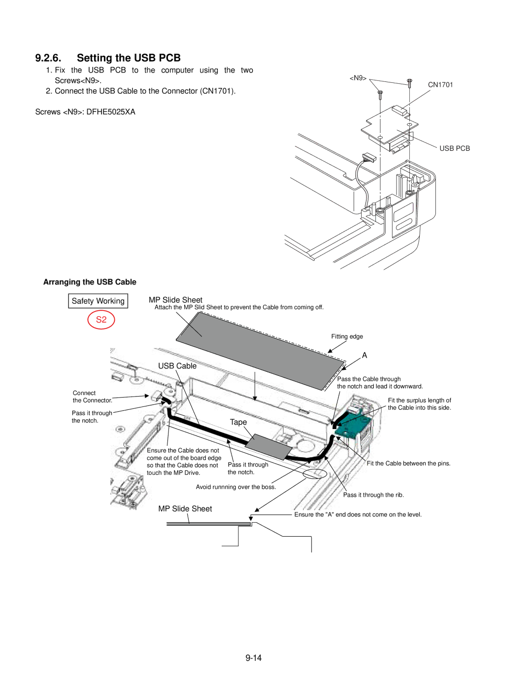
1.Fix the USB PCB to the computer using the two Screws<N9>.
2.Connect the USB Cable to the Connector (CN1701).
Screws <N9>: DFHE5025XA
Arranging the USB Cable
Safety Working | MP Slide Sheet |
| Attach the MP Slid Sheet to prevent the Cable from coming off. |
|
S2
<N9>
Fitting edge
CN1701
USB PCB
Connect
the Connector.![]()
Pass it through the notch.
USB Cable
| Tape |
Ensure the Cable does not |
|
come out of the board edge | Pass it through |
so that the Cable does not | |
touch the MP Drive. | the notch. |
Avoid runnning over the boss.
MP Slide Sheet
A
Pass the Cable through
the notch and lead it downward.
Fit the surplus length of
![]() the Cable into this side.
the Cable into this side.
Fit the Cable between the pins.
Pass it through the rib.
Ensure the "A" end does not come on the level.