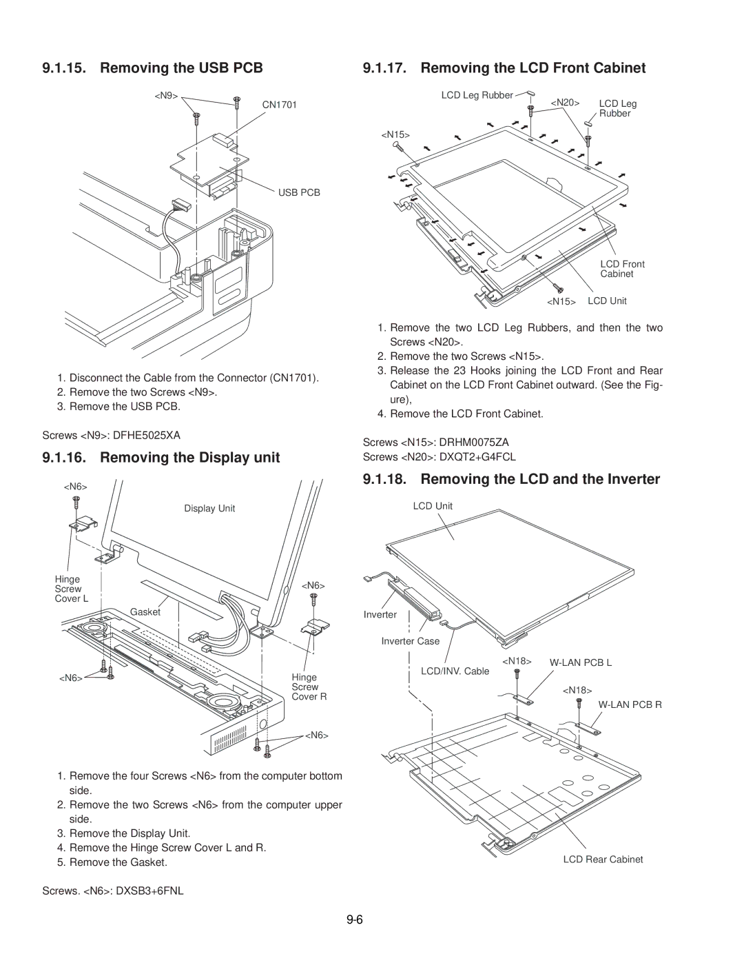
9.1.15. Removing the USB PCB
<N9>
CN1701
USB PCB
1.Disconnect the Cable from the Connector (CN1701).
2.Remove the two Screws <N9>.
3.Remove the USB PCB.
Screws <N9>: DFHE5025XA
9.1.16. Removing the Display unit
<N6>
Display Unit
Hinge | <N6> |
Screw | |
Cover L |
|
| Gasket |
<N6> | Hinge |
| Screw |
| Cover R |
| <N6> |
9.1.17. Removing the LCD Front Cabinet
LCD Leg Rubber | <N20> | LCD Leg |
| ||
|
| Rubber |
<N15>
LCD Front
Cabinet
<N15> LCD Unit
1.Remove the two LCD Leg Rubbers, and then the two Screws <N20>.
2.Remove the two Screws <N15>.
3.Release the 23 Hooks joining the LCD Front and Rear Cabinet on the LCD Front Cabinet outward. (See the Fig- ure),
4.Remove the LCD Front Cabinet.
Screws <N15>: DRHM0075ZA
Screws <N20>: DXQT2+G4FCL
9.1.18. Removing the LCD and the Inverter
LCD Unit
Inverter
Inverter Case
<N18> | |
LCD/INV. Cable |
|
| <N18> |
1.Remove the four Screws <N6> from the computer bottom side.
2.Remove the two Screws <N6> from the computer upper side.
3.Remove the Display Unit.
4.Remove the Hinge Screw Cover L and R.
5. Remove the Gasket. | LCD Rear Cabinet |