9.2.Reassembly Instructions
9.2.1.Attention when
•Please execute writing BIOS ID when you exchange the Main Board.
•You cannot reuse the Conductive Clothes and the heat dissipating parts such as Sheet and Rubber. Use new parts.
9.2.2.Setting the Finger PCB
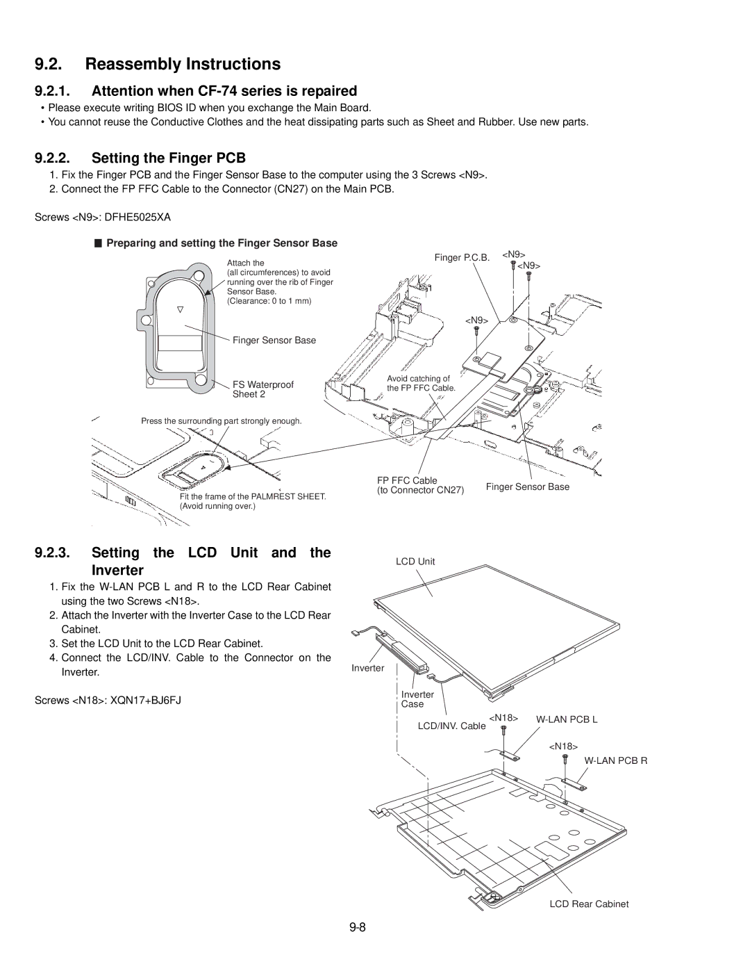
1.Fix the Finger PCB and the Finger Sensor Base to the computer using the 3 Screws <N9>.
2.Connect the FP FFC Cable to the Connector (CN27) on the Main PCB.
Screws <N9>: DFHE5025XA
 Preparing and setting the Finger Sensor Base
Attach the
(all circumferences) to avoid running over the rib of Finger Sensor Base.
(Clearance: 0 to 1 mm)
Finger Sensor Base
FS Waterproof
Sheet 2
Press the surrounding part strongly enough.
Fit the frame of the PALMREST SHEET. (Avoid running over.)
9.2.3.Setting the LCD Unit and the
Inverter
1.Fix the
2.Attach the Inverter with the Inverter Case to the LCD Rear Cabinet.
3.Set the LCD Unit to the LCD Rear Cabinet.
4.Connect the LCD/INV. Cable to the Connector on the Inverter.
Screws <N18>: XQN17+BJ6FJ
Finger P.C.B. <N9> <N9>
<N9>
Avoid catching of the FP FFC Cable.
FP FFC Cable | Finger Sensor Base | |
(to Connector CN27) | ||
|
LCD Unit
Inverter
Inverter
Case
LCD/INV. Cable | <N18> | |
|
| |
|
| <N18> |
LCD Rear Cabinet