5.Remove the DC jack holder on the
6.Remove the LCD cable connectors (CN10,CN11,CN24).
LCD Cable
CN24
CN10
CN11 ![]()
![]()
7.Turn it to arrow and remove the lithium battery connector (CN3), LAN cable connector (CN16) and HDD FPC connector (CN4) and then remove the main board.
Power Knob
LAN SW Knob
![]() Tape
Tape
CN600
LAN ![]()
Cable
Lithium Battery CN3
Cable
CN16 |
6.2.9.Removing the Antenna Board (L,R) and the DC-IN Cable
Preparation : perform the section 6.2.1. , 6.2.2. , 6.2.4. and 6.2.8. first.
1.Remove the antenna cable(L) from the main terminal and the antenna cable(R) from the AUX terminal and then remove the antenna board(L, R) from the bottom case.
2.Remove the
Antenna Board(L) | Antenna Cable(L) |
Cable
CN600
Antenna Cable(R)
![]() Antenna Board(R)
Antenna Board(R)
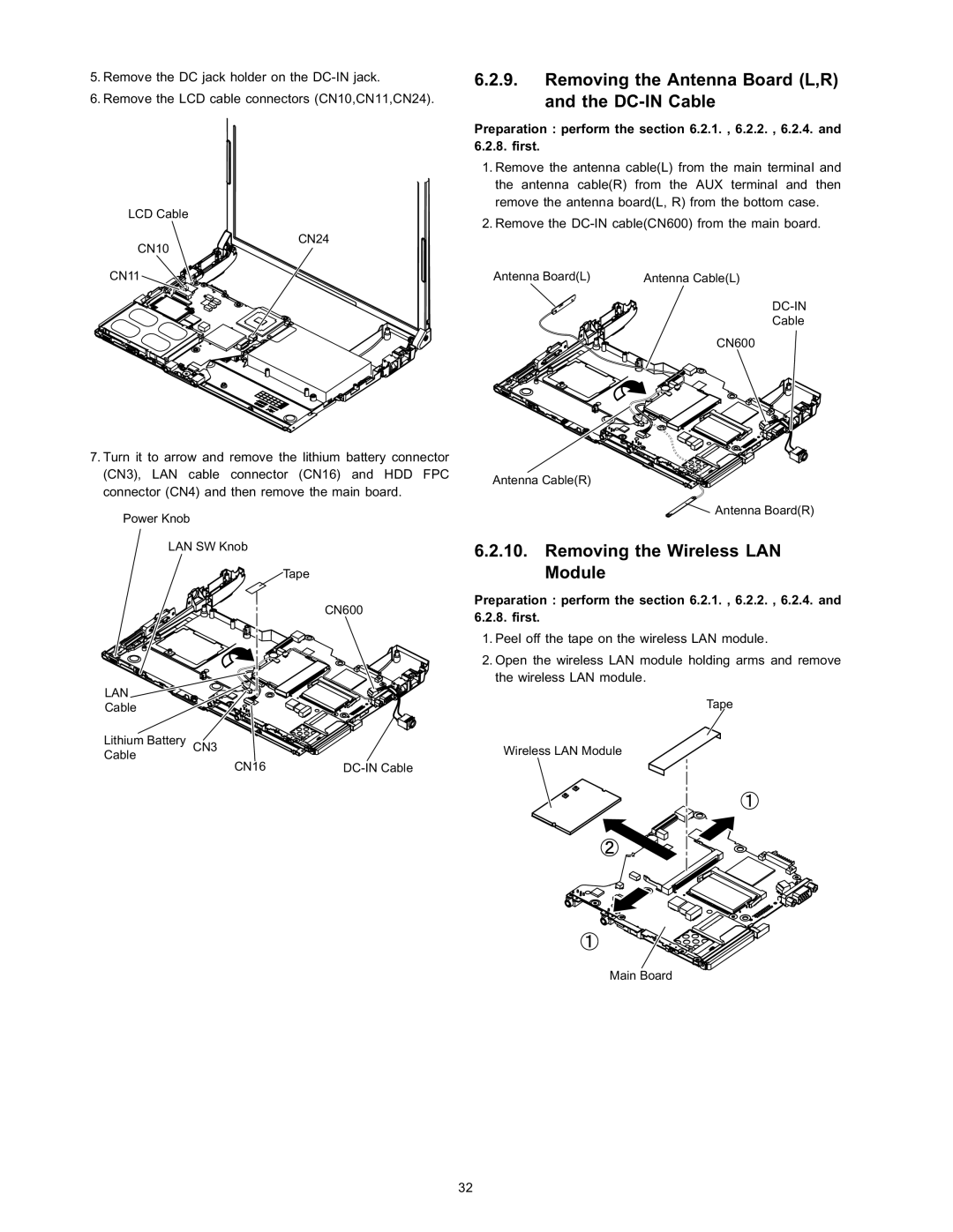
6.2.10.Removing the Wireless LAN Module
Preparation : perform the section 6.2.1. , 6.2.2. , 6.2.4. and 6.2.8. first.
1.Peel off the tape on the wireless LAN module.
2.Open the wireless LAN module holding arms and remove the wireless LAN module.
Tape
Wireless LAN Module
Main Board
32