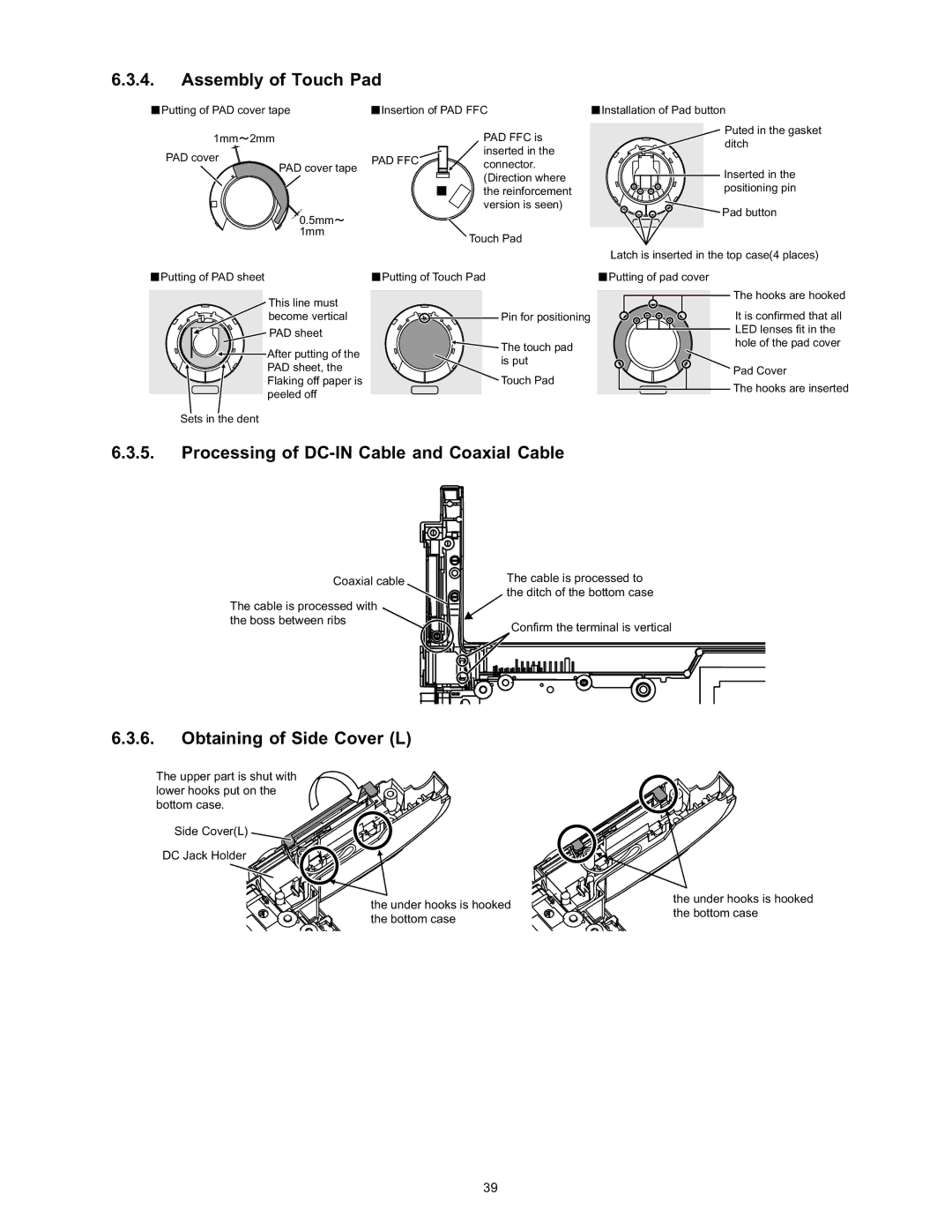
6.3.4.Assembly of Touch Pad
Putting of PAD cover tape | Insertion of PAD FFC | ||
1mm 2mm |
| PAD FFC is | |
PAD cover | PAD FFC | inserted in the | |
connector. | |||
PAD cover tape |
| ||
| (Direction where | ||
|
| ||
|
| the reinforcement | |
|
| version is seen) | |
0.5mm |
|
| |
1mm |
| Touch Pad | |
|
| ||
![]() Installation of Pad button
Installation of Pad button
Puted in the gasket ditch
Inserted in the positioning pin
![]() Pad button
Pad button
Latch is inserted in the top case(4 places)
![]() Putting of PAD sheet
Putting of PAD sheet
This line must become vertical
![]() PAD sheet
PAD sheet
![]() After putting of the
After putting of the ![]() PAD sheet, the Flaking off paper is peeled off
PAD sheet, the Flaking off paper is peeled off
Sets in the dent
| Putting of Touch Pad |
| Putting of pad cover |
![]() Pin for positioning
Pin for positioning
![]() The touch pad is put
The touch pad is put
Touch Pad
The hooks are hooked
It is confirmed that all LED lenses fit in the hole of the pad cover
Pad Cover
The hooks are inserted
6.3.5.Processing of DC-IN Cable and Coaxial Cable
Coaxial cable
The cable is processed with the boss between ribs
The cable is processed to the ditch of the bottom case
Confirm the terminal is vertical
6.3.6.Obtaining of Side Cover (L)
The upper part is shut with lower hooks put on the bottom case.
Side Cover(L)
DC Jack Holder
the under hooks is hooked the bottom case
the under hooks is hooked the bottom case
39