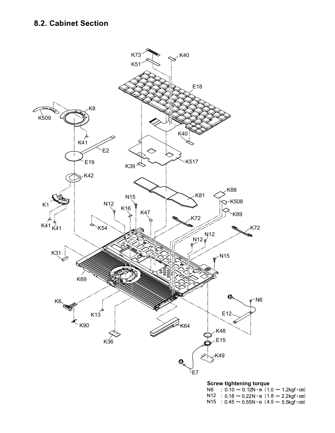
8.2. Cabinet Section
K73
K51
K8
K509
K41
![]() E2
E2
E19
| K39 | |
| K42 | |
| N15 | |
K1 | N12 | |
K16 | ||
|
K40
E18
K40
![]() K517
K517
K88
K81
![]() K508
K508
| K47 |
K41 K41 | K54 |
K72
![]() K89
K89
K72
K31
K69
K6
K13
![]() K90
K90
K36
N12
N12 ![]()
![]() N15
N15
b
![]() N6
N6
E12
![]() K64
K64
K48
E15
![]()
![]() K49
K49
a![]()
![]() E7
E7
Screw tightening torque