6.2.13. Removing the LCD Unit
Preparation : perform the section 6.2.1. , 6.2.2. and 6.2.4. first.
1.Remove the 2 screws (M). Screw(M):DXQT26+D5FNL(N14)
2.Remove the LCD cable from the connector (CN11) of the main board.
3.Remove the inverter cable from the connector (CN10)
4.Remove the touch panel cable from connector (CN24).
Screw(M) ![]()
![]()
LCD CableScrew(M)
CN10 | CN24 |
| |
CN11 |
|
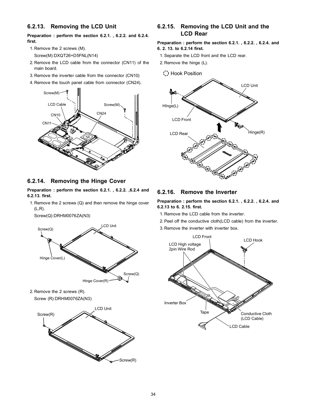
6.2.15.Removing the LCD Unit and the LCD Rear
Preparation : perform the section 6.2.1. , 6.2.2. , 6.2.4. and
6.2. 13. to 6.2.14 first.
1.Separate the LCD front and the LCD rear.
2.Remove the hinge (L).
![]() Hook Position
Hook Position
LCD Unit
HInge(L)
LCD Front
LCD Rear | Hinge(R) |
|
6.2.14. Removing the Hinge Cover
Preparation : perform the section 6.2.1. , 6.2.2. ,6.2.4 and 6.2.13. first.
1.Remove the 2 screws (Q) and then remove the hinge cover (L,R).
Screw(Q):DRHM0076ZA(N3)
LCD Unit
Screw(Q)
Hinge Cover(L)
Screw(Q)
Hinge Cover(R) ![]()
![]()
2.Remove the 2 screws (R). Screw (R):DRHM0076ZA(N3)
LCD Unit
Screw(R)
Screw(R)
6.2.16. Remove the Inverter
Preparation : perform the section 6.2.1. , 6.2.2. , 6.2.4. and 6.2.13 to 6. 2.15. first.
1.Remove the LCD cable from the inverter.
2.Peel off the conductive cloth(LCD cable) from the inverter.
3.Remove the inverter with inverter box.
LCD Front
LCD Hook
LCD High voltage 2pin Wire Rod
Inverter Box
Tape | Conductive Cloth |
| |
| (LCD Cable) |
| LCD Cable |
34