English
9
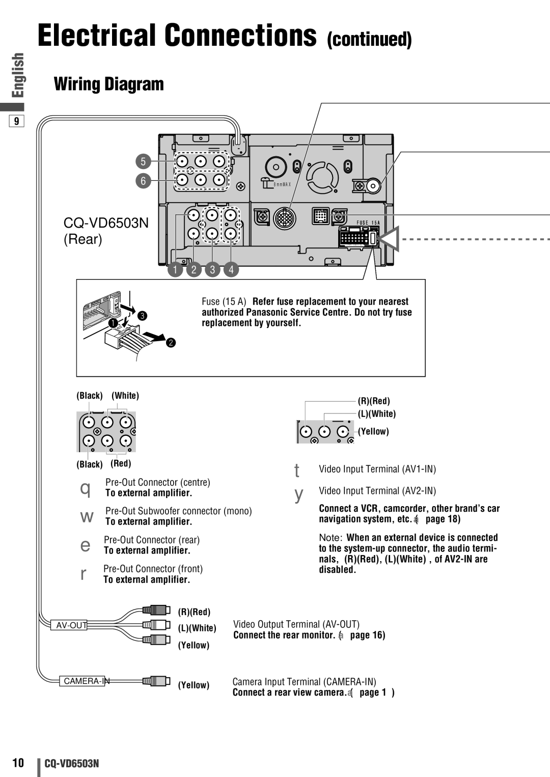
Electrical Connections (continued)
❏Wiring Diagram
5
6 | 8 m m M A X |
CQ-VD6503N (Rear)
1 | 2 | 3 | 4 |
F U S E 1 5 A
> P B T < J A M - S A a
Fuse (15 A) Refer fuse replacement to your nearest authorized Panasonic Service Centre. Do not try fuse replacement by yourself.
(Black) | (White) |
| (R)(Red) |
|
|
| |
|
|
| (L)(White) |
|
|
| (Yellow) |
(Black) | (Red) |
| t Video Input Terminal |
|
| ||
|
| y Video Input Terminal | |
q To external amplifier. |
| ||
|
| Connect a VCR, camcorder, other brand’s car | |
w To external amplifier. |
| navigation system, etc. (a page 18) | |
|
| Note: When an external device is connected | |
e To external amplifier. |
| to the | |
r |
| nals, {(R)(Red), (L)(White)}, of | |
| disabled. | ||
| To external amplifier. |
|
|
| (R)(Red) |
|
|
(L)(White) | Video Output Terminal | ||
| Connect the rear monitor. (a page 16) | ||
| (Yellow) | ||
|
|
| |
(Yellow) | Camera Input Terminal | ||
Connect a rear view camera. (a page 17)
10