Definition of Terms
 Installation Guide
Digital audio output connector (Optical)
EThe digital audio output connector (optical)
N converts electrical signals into optical signals and
Gtransfers them to the amplifier. Consequently, it has
L
a number of features including its immunity fromI
Selectrical interference from external sources and its
Hability to prevent the generation of noise and its
27 minimal effect on the external environment.
Dolby Digital
Dolby Digital is a digital sound compression technique developed by the Dolby Laboratories Licensing Corporation.
MPEG (Moving Picture Experts Group)
MPEG is an international standard format for the compression of motion video as defined by the Moving Picture Experts Group, a working committee which functions under the auspices of the International Standardization Organization and International Electrotechnical Commission. The Group established the MPEG 1 standard in 1991 and the MPEG 2 standard in 1994. MPEG 2 builds on MPEG 1 with many improvements, and it yields a higher picture quality level.
Pan & Scan screen
WARNING | N | |
| E | |
| G | |
The installation information is designed for experienced installers and is not | L | |
I | ||
intended for | S | |
the potential dangers involved in attempting to install this product. | H | |
28 | ||
Any attempt to install this product in a motor car by anyone other than a qualified | ||
| ||
installer could cause damage to the electrical system and could result in serious |
| |
personal injury or death. |
| |
|
|
Supporting
Manufactured under license from Dolby Laboratories. “Dolby” and the
Interactive DVD
An interactive DVD is DVD software which includes multiple angles, multiple plot endings, etc.
Letterbox screen
This refers to a screen on which the playback
This refers to a screen on which the playback picture of
Playback control (Video CD)
If the Video CD has “With Playback Control” or others written on the disc surface or on the jacket, the scenes or information to be viewed (or listened to) can be selected interactively with the screen by looking at the menu shown on the screen.
In these instructions, playback using the menu screen is referred to as the “menu play” for video CDs. This player supports Video CDs with playback
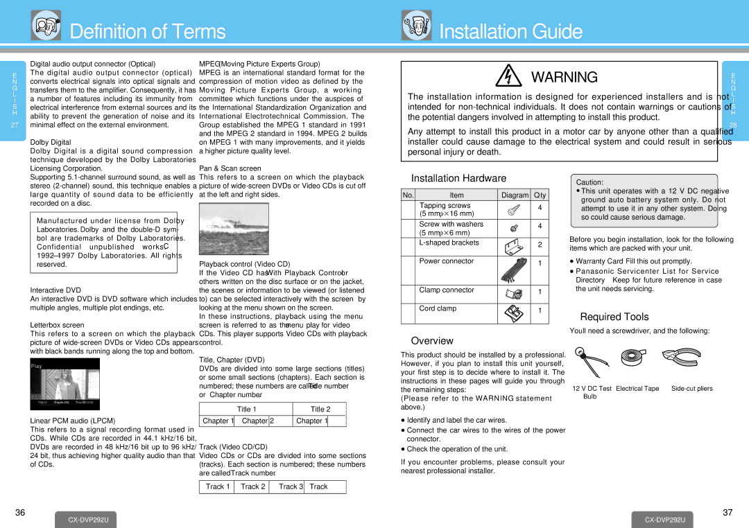
❐Installation Hardware
No. | Item | Diagram Q’ty |
1 | Tapping screws | 4 |
| (5 mm·k16 mm) |
|
2 | Screw with washers | 4 |
| (5 mm·k6 mm) |
|
3 | 2 | |
4 | Power connector | 1 |
5 | Clamp connector | 1 |
6 | Cord clamp | 1 |
Caution:
≥This unit operates with a 12 V DC negative ground auto battery system only. Do not attempt to use it in any other system. Doing so could cause serious damage.
Before you begin installation, look for the following items which are packed with your unit.
≥Warranty Card…Fill this out promptly.
≥Panasonic Servicenter List for Service Directory …Keep for future reference in case the unit needs servicing.
❐Required Tools
You’ll need a screwdriver, and the following:
picture of
Linear PCM audio (LPCM)
This refers to a signal recording format used in CDs. While CDs are recorded in 44.1 kHz/16 bit, DVDs are recorded in 48 kHz/16 bit up to 96 kHz/ 24 bit, thus achieving higher quality audio than that of CDs.
control.
Title, Chapter (DVD)
DVDs are divided into some large sections (titles) or some small sections (chapters). Each section is numbered; these numbers are called “Title number” or “Chapter number”.
| Title 1 |
| Title 2 | ||
| …… | Chapter 1 |
| …… | |
Chapter 1 | Chapter 2 |
| |||
|
|
|
|
|
|
Track (Video CD/CD)
Video CDs or CDs are divided into some sections (tracks). Each section is numbered; these numbers are called “Track number”.
Track 1 | Track 2 | Track 3 | Track …… |
❐Overview
This product should be installed by a professional. However, if you plan to install this unit yourself, your first step is to decide where to install it. The instructions in these pages will guide you through the remaining steps:
(Please refer to the “WARNING” statement above.)
≥Identify and label the car wires.
≥Connect the car wires to the wires of the power connector.
≥Check the operation of the unit.
If you encounter problems, please consult your nearest professional installer.
12 V DC Test | Electrical Tape | |
Bulb |
|
|
36
37
|
