Installation Guide (continued)
| ❐ Identify All Leads |
E | The first step in installation is to identify all the car |
N | |
G | wires you’ll use when hooking up your sound |
L | system. |
I | As you identify each wire, we suggest that you label |
S | |
H | it using masking tape and a permanent marker. |
29This will help avoid confusion when making connections later.
Note:
≥Do not connect the power connector to the unit until you have made all connections. If there are no plastic caps on the stereo hooking wires, insulate all exposed leads with electrical tape until you are ready to use them. Identify the leads in the following order.
Power Lead
If your car has a radio or is
Cut the connector wires one at a time from the plug (leaving the leads as long as possible) so that you can work with individual leads.
Turn the ignition on to the accessory position, and ground one lead of the test bulb to the chassis.
Touch the other lead of the test bulb to each of the exposed wires from the cut radio connector plug. Touch one wire at a time until you find the outlet that causes the test bulb to light.
Now turn the ignition off and then on. If the bulb also turns off and on, that outlet is the car power lead.
If your car is not wired for an audio unit:
Go to the fuse block and find the fuse port for radio (RADIO), accessory (ACC), or ignition (IGN).
Battery Lead
If your DVD player has a yellow lead, you will need to locate the car’s battery lead. Otherwise you may ignore this procedure. (The yellow battery lead provides continuous power to maintain a clock, memory storage, or other function.)
If your car has a radio or is pre-wired for one:
With the ignition and headlights off, identify the car battery lead by grounding one lead of the test bulb to the chassis and checking the remaining exposed wires from the cut radio connector plug.
If your car is not wired for an audio unit:
Go to the fuse block and find the fuse port for the battery which is usually marked BAT.
❐Connect All Leads
Now that you have identified all the wires in the car, you’re ready to begin connecting them to the DVD player wires. The electrical connections (➡ pages
We strongly recommend that you test the unit before making a final installation.
You can set the unit on the floor and make temporary connections to test the unit. Use electrical tape to cover all exposed wires.
Important:
≥Connect the red power lead last, after you have made and insulated all other connections.
Ground
Connect the black ground lead of the power connector to the metal car chassis.
Battery
Connect the yellow battery lead to the correct radio wire or to the battery fuse port on the fuse block.
Power
Connect the red power lead to the correct power cord according to your system configuration by referring to the wiring diagram .
If the unit functions properly with all these connections made, disconnect the wires and proceed to the final installation.
❐Final Installation
Lead Connections
Connect all wires, making sure that each connection is insulated and secure. Bundle all loose wires and fasten them with tape so they won’t fall down later.
Congratulations! After making a few final checks, you’re ready to enjoy your mobile DVD player.
❐Final Checks
1.Make sure that all wires are properly connected and insulated.
2.Turn on the ignition to check the unit for proper operation.
If you have difficulties, consult your nearest authorized professional installer for assistance.
❐Preparation
≥We strongly recommend that you wear gloves for installation work to protect yourself from injuries.
≥Disconnect the cable from the negative - battery terminal (see caution below).
≥Unit should be installed in a horizontal position with the front end up at a convenient angle, but not more than 30o.
Less than 30x
Caution:
≥Do not disconnect the battery terminals of a car with a trip or navigational computer since all user settings stored in memory will be lost. Instead take extra care with installing the unit to prevent shorts.
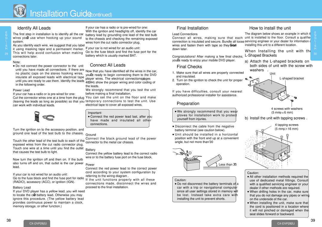
❐How to install the unit
The diagram below shows an example in which this unit is installed to the floor. Consult a qualified servicing engineer or your dealer for information on installing this unit to a different location.
When Installing the unit with the
a)Attach the
washers 2.
Unit
3
24 screws with washers (5 mm·k6 mm)
b)Install the unit with tapping screws 1.
14 tapping screws  (5 mm·k16 mm)
Caution:
≥All other installation methods required the use of dedicated metal fittings. Consult with a qualified servicing engineer or your dealer if other methods are required.
≥When drilling holes in the car, make sure that you do not damage any pipes or wiring on the underside of the car.
≥When installing the unit, make sure that the cord is positioned in a location where it will not pinched or damaged when the seat slides forward or backward.
E
N
G
L
I
S
H
30
38
CX-DVP292U
39