Connections
|
|
|
|
| 1 Aerial |
|
|
|
| Aerial infeed line | |
|
| RF IN | |||
| Aerial input | ||||
|
|
|
|
| RF IN |
|
|
|
| COMPONENT VIDEO OUT | Y |
|
| L |
|
| P |
|
|
|
|
| |
| OPTICAL |
|
| S VIDEO OUT |
|
|
|
|
|
| |
|
| R | VIDEO OUT |
| P |
AC IN | DIGITALAUDIO OUT |
|
|
| RF OUT |
AUDIO OUT |
|
|
| ||
(PCM/BITSTREAM) |
| AV2(DECODER/EXT) | AV 1 (TV) |
| |
| AC IN~ |
|
|
| RF OUT |
|
|
|
|
| Aerial output |
4AC Mains lead
| 3 | |
VT | Necessary for TV | |
with Q Link | ||
|
Aerial input
2 RF Coaxial cable
4AC Mains lead
|
|
|
| 1Aerial |
|
|
|
| Aerial infeed line |
| AUDIO- | VIDEO- | RF IN | |
| Output | Output | Aerial input | |
|
|
|
| RF IN |
|
|
|
| COMPONENT VIDEO OUTY |
|
| L |
| P |
| OPTICAL |
|
| S VIDEO OUT |
|
|
|
| |
|
| R | VIDEO OUT | P |
AC IN | DIGITALAUDIO OUT |
|
| RF OUT |
AUDIO OUT |
|
| ||
(PCM/BITSTREAM) |
| AV2(DECODER/EXT) | AV 1 (TV) | |
AC IN~ | L |
|
| RF OUT |
|
|
|
| Aerial output |
| R |
| VIDEO OUT |
|
| AUDIO OUT |
|
|
|
4AC Mains lead
| 3 Audio/Video cable | ||
| Video | Yellow | |
VT | L | White | |
R | Red | ||
| |||
Audio/Video input
Aerial input | 2 RF Coaxial cable |
|
4AC Mains lead
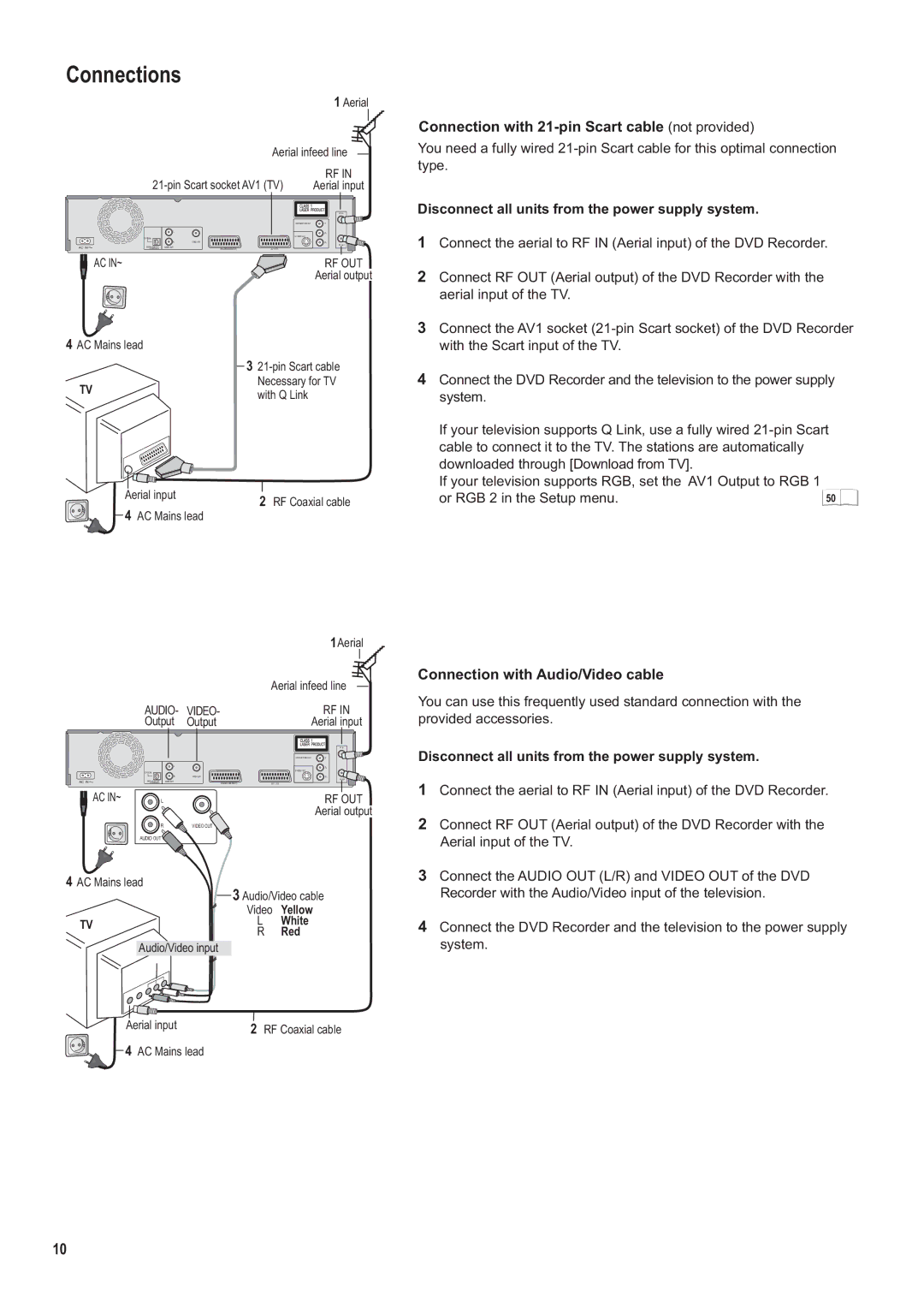
Connection with 21-pin Scart cable (not provided)
You need a fully wired
Disconnect all units from the power supply system.
1Connect the aerial to RF IN (Aerial input) of the DVD Recorder.
2Connect RF OUT (Aerial output) of the DVD Recorder with the aerial input of the TV.
3Connect the AV1 socket
4Connect the DVD Recorder and the television to the power supply system.
If your television supports Q Link, use a fully wired
If your television supports RGB, set the AV1 Output to RGB 1 |
|
or RGB 2 in the Setup menu. | 50 |
Connection with Audio/Video cable
You can use this frequently used standard connection with the provided accessories.
Disconnect all units from the power supply system.
1Connect the aerial to RF IN (Aerial input) of the DVD Recorder.
2Connect RF OUT (Aerial output) of the DVD Recorder with the Aerial input of the TV.
3Connect the AUDIO OUT (L/R) and VIDEO OUT of the DVD Recorder with the Audio/Video input of the television.
4Connect the DVD Recorder and the television to the power supply system.
10
