PREPARATION | – Power – |
Connecting to the AC adapter
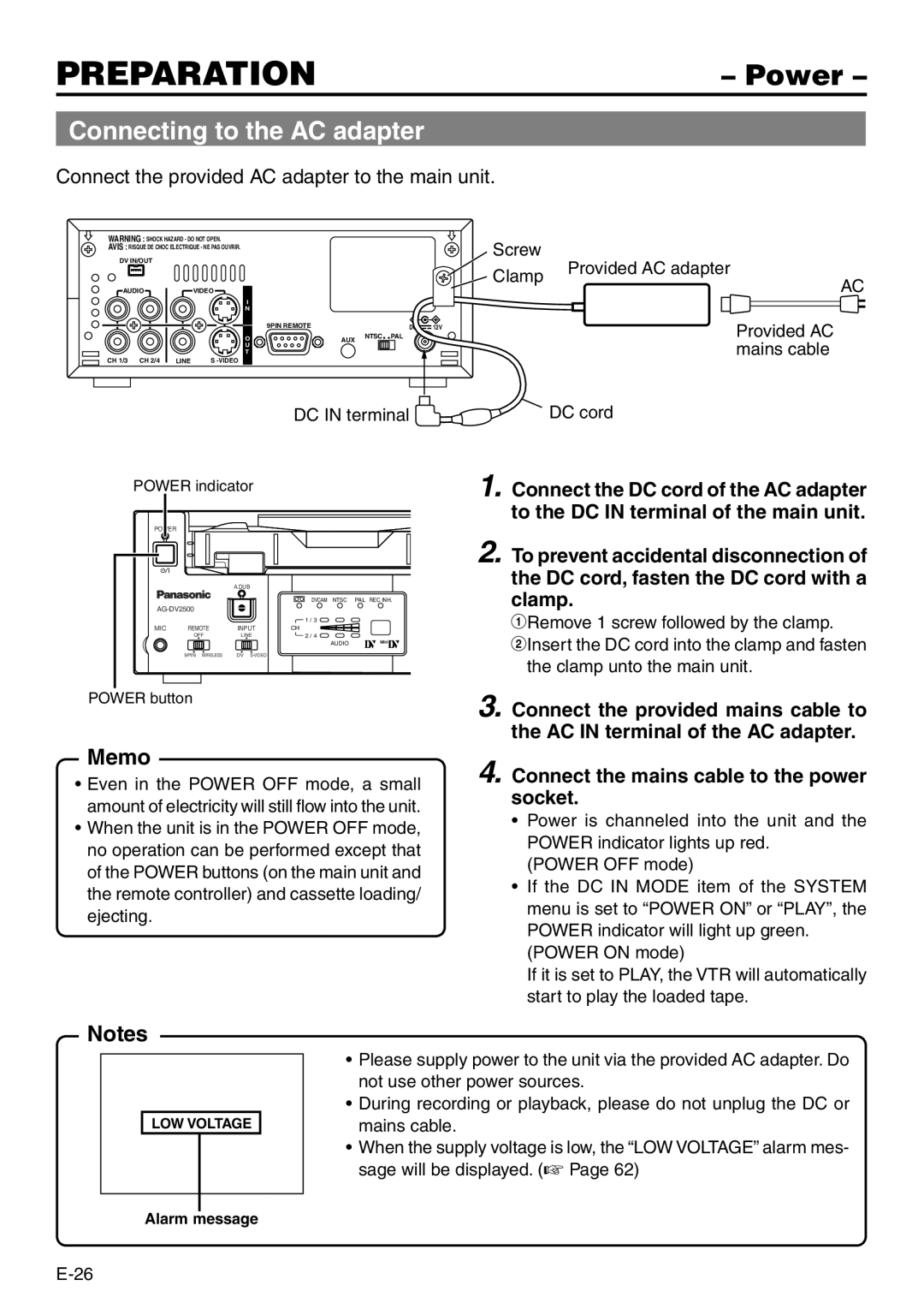
Connect the provided AC adapter to the main unit.
WARNING : SHOCK HAZARD - DO NOT OPEN. |
|
|
| Screw |
| ||
AVIS : RISQUE DE CHOC ELECTRIQUE - NE PAS OUVRIR. |
|
|
|
| |||
|
|
|
|
| |||
DV IN/OUT |
|
|
|
|
|
| Provided AC adapter |
|
|
|
|
|
| Clamp | |
|
|
|
|
|
|
| |
AUDIO |
| VIDEO |
|
|
|
|
|
|
| I |
|
|
|
|
|
|
| N |
|
|
|
|
|
|
| 9PIN REMOTE |
|
| DC | 12V |
|
|
| O | AUX | NTSC | PAL |
|
|
|
| U |
|
|
|
|
|
|
| T |
|
|
|
|
|
CH 1/3 CH 2/4 | LINE | S |
|
|
|
|
|
AC
Provided AC mains cable
DC IN terminal 
POWER indicator
POWER
A.DUB
DVCAM NTSC PAL REC INH.
|
|
| 1 / 3 |
MIC | REMOTE | INPUT | CH |
| OFF | LINE | 2 / 4 |
|
|
| AUDIO |
| 9PIN WIRELESS | DV |
|
POWER button
Memo
•Even in the POWER OFF mode, a small amount of electricity will still flow into the unit.
•When the unit is in the POWER OFF mode, no operation can be performed except that of the POWER buttons (on the main unit and the remote controller) and cassette loading/ ejecting.
Notes
LOW VOLTAGE
•Please supply power to the unit via the provided AC adapter. Do not use other power sources.
•During recording or playback, please do not unplug the DC or mains cable.
•When the supply voltage is low, the “LOW VOLTAGE” alarm mes- sage will be displayed. (☞ Page 62)
Alarm message
