Model No. WV-CW484 Series
Do not Remove Cover or Back No USER-SERVICEABLE Parts Inside
English
Important Safety Instructions
Limitation of Liability
Disclaimer of Warranty
Preface
Features
Contents
Precautions
Do not aim the apparatus at strong light sources
Observe the following for installation
Avoid installing in the following locations
Installing place
What to do if Over Heat appears on the display
Mounting screws
Consumable parts
Major Operating Controls and Their Functions
3LED indicator
Power cable 12 V DC or 24 V AC Cautions
Azimuth Angle adjuster
2Optional heater connector 6 pin female
Lens Mounting WV-CW484FK, CW484SK
Installations
Using Mounting Bracket
Fixing the camera attachment to the mounting bracket
Using Mounting Bracket
How to mount the camera
Using a Junction Box
Protrusion Screw hole of camera attachment Rear screw
Camera fixing screw
Winding the provided butyl tape
Waterproof Process
Waterproof processing of cable connection
Downward
Image Adjustment
How to use a variable focal lens
Zoom/focus adjustment
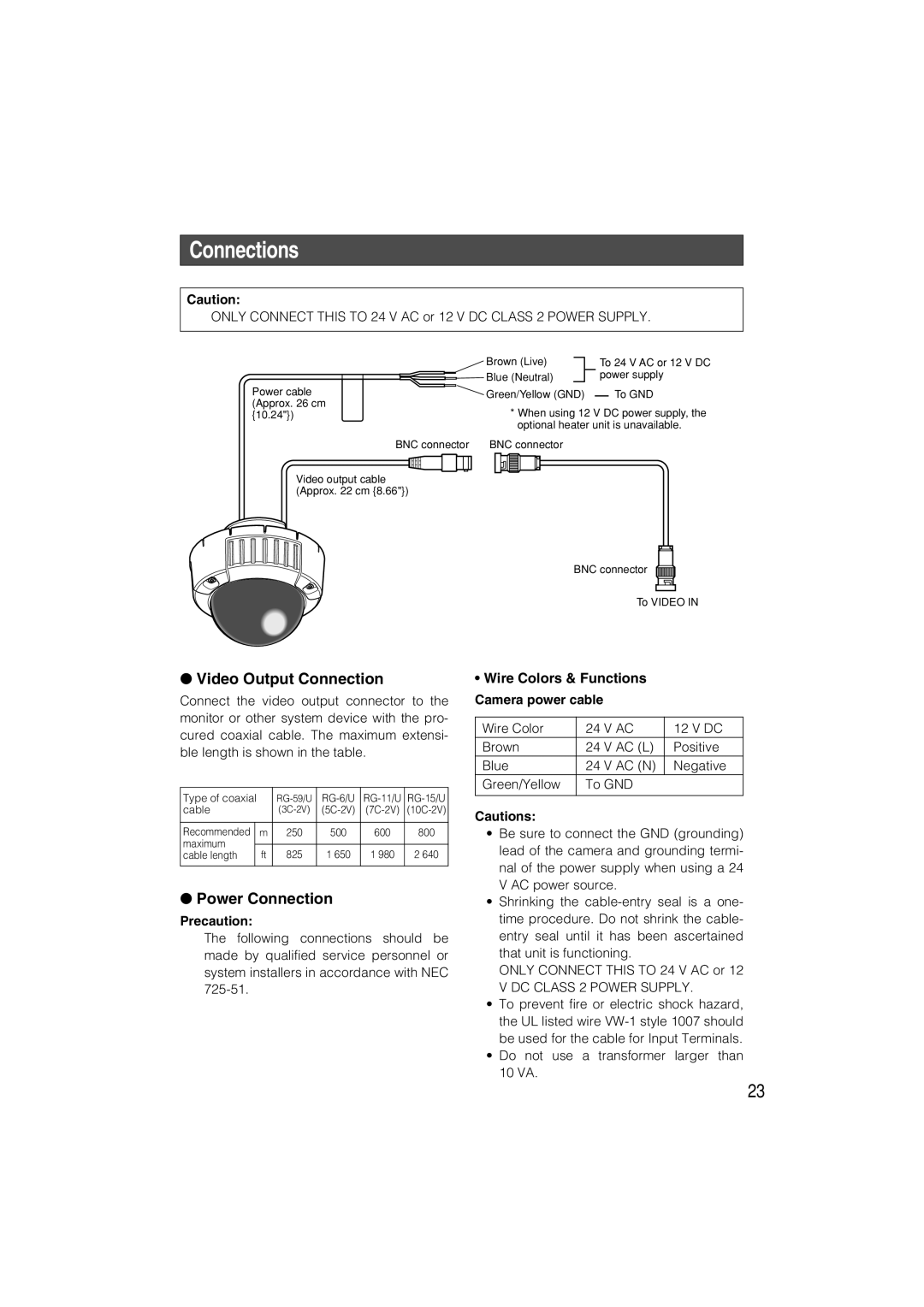
Connections
Power Connection
Precaution
Wire Colors & Functions Camera power cable
Cable Length and Wire Gauge
Introduction
Installation
Optional Heater Unit WV-CW4H
Hints
Before Back-focus Adjustment
For Adjusting the Focus
For Using General Vari-focal Lenses
Setup item Description
About Setup Menus
Settings items of the camera setup
Language
Basic operation
Page
Camera Identification Setting Camera ID
Setting Procedures
Language Setup Language Setup
Super Dynamic 3 Function SUPER-D3
Light Control Mode Setting ALC
ALC Mode with SUPER-D3 on
ALC Mode with SUPER-D3 OFF
Shutter Speed Setting Shutter
Electronic Sensitivity Enhancement Sens UP
Gain Control Setting AGC
White Balance Setting White BAL
Synchronization Setting Sync
Available time second 2, 5, 10
Motion Detection Setting Motion DET
AWC Setting
Manual Fine Adjustment
Motion Detector
Demo Mode
About MODE2 of Motion Detection
Digital Noise Reduction Setting DNR
Resolution Setting Resolution
Black and White Mode Setting BW Mode
Privacy Zone Setting Privacy Zone
Auto Image Stabilizer Stabilizer
Electronic Zoom EL-ZOOM
Camera Picture Upside Down Positioning UPSIDE-DOWN
Lens
Back-focus Setting BACK-FOCUS Setup
Chroma Level Setting Chroma Gain
Special Menu Special Setup
Pixel Compensation Setting PIX OFF
Aperture Gain Setting AP Gain
Pedestal Level Setting Pedestal
Chroma Phase Hue Setting HUE
Serial number of the camera will be displayed
To reset to the default settings Camera Reset
Symptom
Troubleshooting
Lens WV-CW484S, WV-CW484F
Specifications
General specifications
Camera
ABF, MANUAL, AUTO/PRESET/FIX
Standard Accessories
Optional Accessories
Version Française
Instructions de sécurité importantes
Déni de la garantie
Limitation de responsabilité
Caractéristiques dominantes
Préface
Table DES Matières
Ne jamais essayer de démonter cette caméra vidéo
Mesures de précaution
Cet appareil na pas dinterrupteur dalimentation
Pour avoir lassurance dobtenir des performances stables
Propos de lappareil déshumidificateur
Éviter toute installation dans les emplace- ments suivants
Emplacement dinstallation
Vis dinstallation
Principaux organes de commande et fonctions
0Vis de blocage de caméra vidéo
Câble de sortie vidéo avec le connecteur BNC
Vis de verrouillage dinclinaison
Azimut dispositif de réglage angulaire
Monture dobjectif WV-CW484FK, CW484SK
Installations
En utilisant une boîte de jonction
Installations
En utilisant la platine de fixation dinstallation
TOP
Utilisation d’une boîte de raccordement
Comment installer la caméra vidéo
En utilisant la platine de fixation dinstallation
Page
Remarques
Enroulement de la bande en butyle fournie
Opération de mise sous étanchéité
Mise sous étanchéité du raccordement de câble
Vers le bas
Réglage de limage
Comment se servir dun objectif à focale variable
Réglage de zoom ou de mise au point
Couleurs des fils et fonctions
Branchements
Connexion de sortie vidéo
Raccordement dalimentation
DE Courant Alternatif
Longueur de câble et calibre pour fils
Appareil de chauffage optionnel WV-CW4H
Pour régler la mise au point
Conseils
Avant dexécuter le réglage de tirage arrière
Configuration
Propos des menus de configuration
Ajuste le niveau de chrominance densité de la Couleur
Remarque
Utilisation de base
Remarques
Paramétrage didentification de la caméra vidéo Camera ID
Configuration de la langue
Procédures de réglage
SUPER-D3 on Valide la
Paramétrage de mode de contrôle de lumière ALC
Mode ALC avec la fonction SUPER-D3 activée
Fonction Super Dynamic 3 SUPER-D3
Réglage de la vitesse d’obturation Shutter
Mode ALC avec la fonction SUPER-D3 OFF
Accroissement de la sensibilité électronique Sens UP
Paramétrage de contrôle de gain AGC
Réglage de balance des blancs White BAL
Signal de sortie vidéo de la caméra vidéo à
Ajuster et le signal vidéo de sortie de
Réglage de synchronisation Sync
Réglage précis et manuel
Paramétrage de la détection de mouvement Motion DET
Paramétrage de AWC
Détecteur de mouvement
Mode de démonstration
Propos du MODE2 de la détection de mouvement
Paramétrage de résolution Resolution
Paramétrage du mode monochromatique BW Mode
Paramétrage de la réduction de bruit numérique DNR
Paramétrage de zone de confidentialité Privacy Zone
Stabilisateur dimage automatique Stabilizer
Zoom électronique EL-ZOOM
Paramétrage de tirage arrière BACK-FOCUS Setup
18-1. Réglage de niveau de chrominance
Menu spécial Special Setup
Paramétrage de compensation de pixel PIX OFF
18-4. Réglage de phase de chrominance teinte HUE
18-2. Réglage de gain douverture AP Gain
Le numéro de série de cette caméra vidéo sera affiché
Symptômes
Dépannage
Objectif WV-CW484S, WV-CW484F
Caractéristiques techniques
Caméra vidéo
ENGLISH, FRENCH, GERMAN, SPANISH, Italian
Accessoires standard
Accessoires optionnels
Panasonic Canada Inc