| 1 |
|
| 55 |
|
| 2 | 54 |
|
| 95 |
FIGURE 21 | 71 |
|
|
|
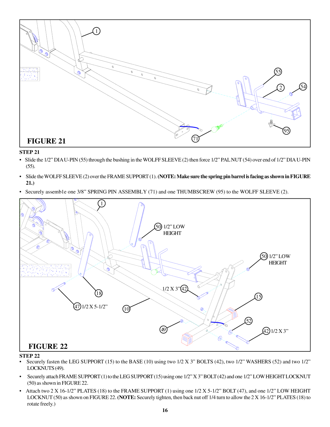
STEP 21
•Slide the 1/2”
•Slide the WOLFF SLEEVE (2) over the FRAME SUPPORT (1). (NOTE: Make sure the spring pin barrel is facing as shown in FIGURE 21.)
•Securely assemb1e one 3/8” SPRING PIN ASSEMBLY (71) and one THUMBSCREW (95) to the WOLFF SLEEVE (2).
1 |
|
|
| 50 1/2” LOW |
|
| HEIGHT |
|
|
| 50 1/2” LOW |
|
| HEIGHT |
18 | 1/2 X 3” 42 |
|
| 15 | |
|
| |
47 1/2 X | 10 |
|
|
| |
|
| 52 |
| 49 | 42 1/2 X 3” |
FIGURE 22 |
|
|
STEP 22
•Securely fasten the LEG SUPPORT (15) to the BASE (10) using two 1/2 X 3” BOLTS (42), two 1/2” WASHERS (52) and two 1/2” LOCKNUTS (49).
•Securely attach FRAME SUPPORT (1) to the LEG SUPPORT (15) using one 1/2” X 3” BOLT (42) and one 1/2” LOW HEIGHT LOCKNUT (50) as shown in FIGURE 22.
•Attach two 2 X
16