FIGURE 36 | 48 | 11 |
|
|
|
| |
|
|
| 91 |
| 79 |
| 51 |
|
|
| |
|
| 66 |
|
SEE DETAIL 36 |
| 3/8 X | 38 |
|
| ||
|
|
| DETAIL 36 |
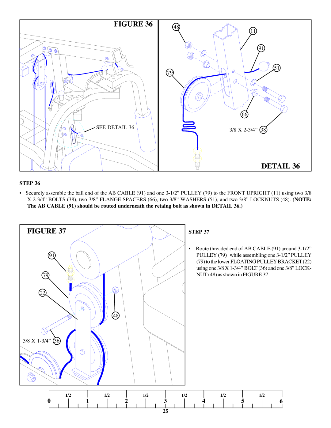
STEP 36
•Securely assemble the ball end of the AB CABLE (91) and one
The AB CABLE (91) should be routed underneath the retaing bolt as shown in DETAIL 36.)
FIGURE 37 |
|
|
| STEP 37 |
|
| |
|
|
|
|
| • Route threaded end of AB CABLE (91) around | ||
91 |
|
|
| PULLEY (79) while assembling one | |||
|
|
|
|
| (79) to the lower FLOATING PULLEY BRACKET (22) | ||
|
|
|
|
| using one 3/8 X | ||
79 |
|
|
|
| NUT (48) as shown in FIGURE 37. |
| |
22 |
|
|
|
|
|
|
|
|
|
| 48 |
|
|
|
|
3/8 X | 36 |
|
|
|
|
|
|
0 | 1/2 | 1/2 | 1/2 | 1/2 | 1/2 | 1/2 | 6 |
| 1 | 2 | 3 | 4 | 5 | ||
|
|
|
| 25 |
|
|
|