| UPPERFLOATINGPULLEYBRACKET |
| ADJUSTMENT |
ADJUSTMENT | LOWERFLOATING |
| PULLEYBRACKET |
ADJUSTMENT |
|
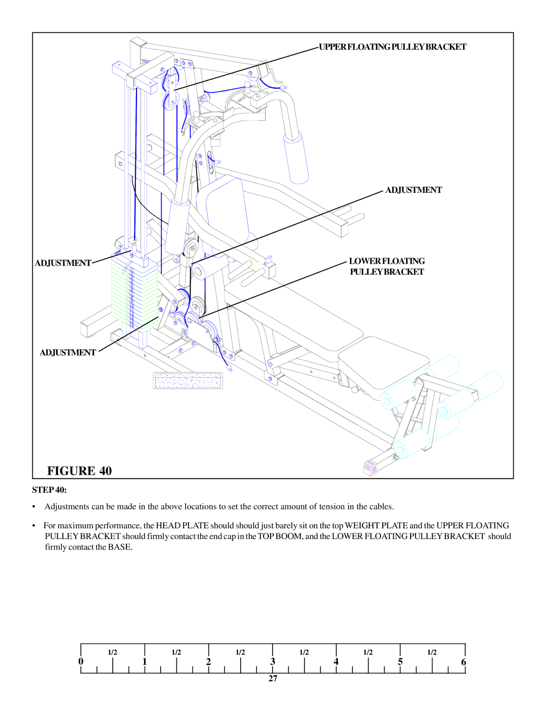
FIGURE 40 |
|
STEP 40:
•Adjustments can be made in the above locations to set the correct amount of tension in the cables.
•For maximum performance, the HEAD PLATE should should just barely sit on the top WEIGHT PLATE and the UPPER FLOATING PULLEY BRACKET should firmly contact the end cap in the TOP BOOM, and the LOWER FLOATING PULLEY BRACKET should firmly contact the BASE.
| 1/2 |
| 1/2 |
| 1/2 |
| 1/2 |
| 1/2 |
|
| 1/2 |
0 | 1 | 2 | 3 | 4 | 5 | 6 | ||||||
27
