800 553-NETS Fax
Release Last Updated May 15
Cisco Systems, Inc 170 West Tasman Drive San Jose, CA
Cisco AC/DC Power System User Guide
Cisco AC/DC Power System User Guide, Release
Turn the television or radio antenna until the interference stops
1.1.1
Where to Find Safety and Warning Information
C O N T E N T S
1.1.2
2.2.1
Install the 1 RU Distribution Shelf
2.1.4
2.2.2
Remove Modules
Statement 1030-Equipment Installation
Add Modules
Statement 1017-Restricted Area
Contents Cisco AC/DC Power System User Guide, R1.0
Installing a Circuit Breaker
Ground Symbol
Installing 1 RU DC Cabling
Alarm Board Connection Points
Removing the 1 RU Distribution Shelf Faceplate
Installing Fuses
Circuit Breaker On/Off Positions
Removing the Controller Faceplate
Cabling Specifications
Parts List
System Configurations
Status and Alarm Specifications
Tables Cisco AC/DC Power System User Guide, R1.0
Audience
About this Guide
Document Objectives
Document Organization
Application
Document Conventions
Convention
boldface
Cisco.com
Where to Find Safety and Warning Information
Obtaining Documentation
Ordering Documentation
Obtaining Technical Assistance
Documentation Feedback
Cisco Technical Support Website
Submitting a Service Request
Definitions of Service Request Severity
Obtaining Additional Publications and Information
http//cisco.com/univercd/cc/td/doc/pcat
1.1 System Description
Introduction
C H A P T E R
System LCD
1.1.1 System Shelf
Circuit Breaker Positions
System GMT Status Fuse Controls Panel 1RU Distribution Shelf
System
1.1.2 Rectifier Modules
Circuit Breaker Positions
Status
Figure 1-4 CSCO-PWR-RECT Rectifier Module
1.1.3 GMT Fuses
1.1.4 1 RU Distribution Shelf
Figure 1-5 GMT Fuse Panel
Figure 1-6 1 RU Distribution Shelf
1.1.5 System Configurations
Figure 1-7 Circuit Breaker
Table 1-2 Cabling Specifications
1.1.6 General Specifications
Table 1-1 System Configurations
Table 1-3 Electrical Specifications
Overcurrent output
1.2 Safety Recommendations
Statement
1.2.1 Installation Warning
1.2.2 Operating Temperature Warnings
1-10
1.2.3 Electrical Safety Warnings
Figure 1-9 Two-Inch Clearance Around Front Ventilation Opening
1-11
Ensure that the proper size circuit protection is being used
Cisco AC/DC Power System User Guide, R1.0
1-12
1.2.3 Electrical Safety Warnings
Chapter
2.1.1 Ground Symbol
System Installation
2.1 Pre-Installation
2.1.2 Tools Required
2.1.4 Installation Materials
2.1.3 Installation and Commissioning Checklist
Supplied Materials for the System Shelf
Supplied Materials for the 1 RU Distribution Shelf
2.2 Install AC/DC Power System Components
Table 2-1 Supplied Materials for the System Shelf continued
Non-Supplied Materials
2.2.1 Install the System Shelf
Figure 2-2 Cisco AC/DC Power System Front View
Figure 2-4 Installing the System Shelf
2.2.2 Install the 1 RU Distribution Shelf
Figure 2-5 1 RU Distribution Cable Dressing
2.2.2.1 Install the Communications Cabling Optional
Figure 2-6 1 RU Distribution Shelf Installation
2.2.2.2 Install the DC Power Cabling Optional
Figure 2-7 1 RU Distribution Shelf Alarm Cabling
2.2.3 Install the Ground Cable
Figure 2-8 Installing 1 RU DC Cabling
2.2.3.2 Install the System Shelf Ground
2.2.3.1 Install the Cabinet/Rack Ground
2-10
2-11
2.2.3.3 Install the 1 RU Distribution Shelf Ground
Figure 2-10 Installing the System Shelf Ground
2.3 Install AC Power Cables
2-12
2-13
International Electromechanical Commission IEC
Chapter 2 System Installation 2.3 Install AC Power Cables
2-14
Figure 2-12 Installing the AC Cable Shelf
Cisco AC/DC Power System User Guide, R1.0
2-15
Step 9 AC cabling should be tied off inside the cabinet/rack
Minimum AC Wire
2.3.1 Install the Rectifiers
2-16
Single Phase
2-17
Figure 2-14 Installing a Rectifier
2.4 Install Circuit Breakers
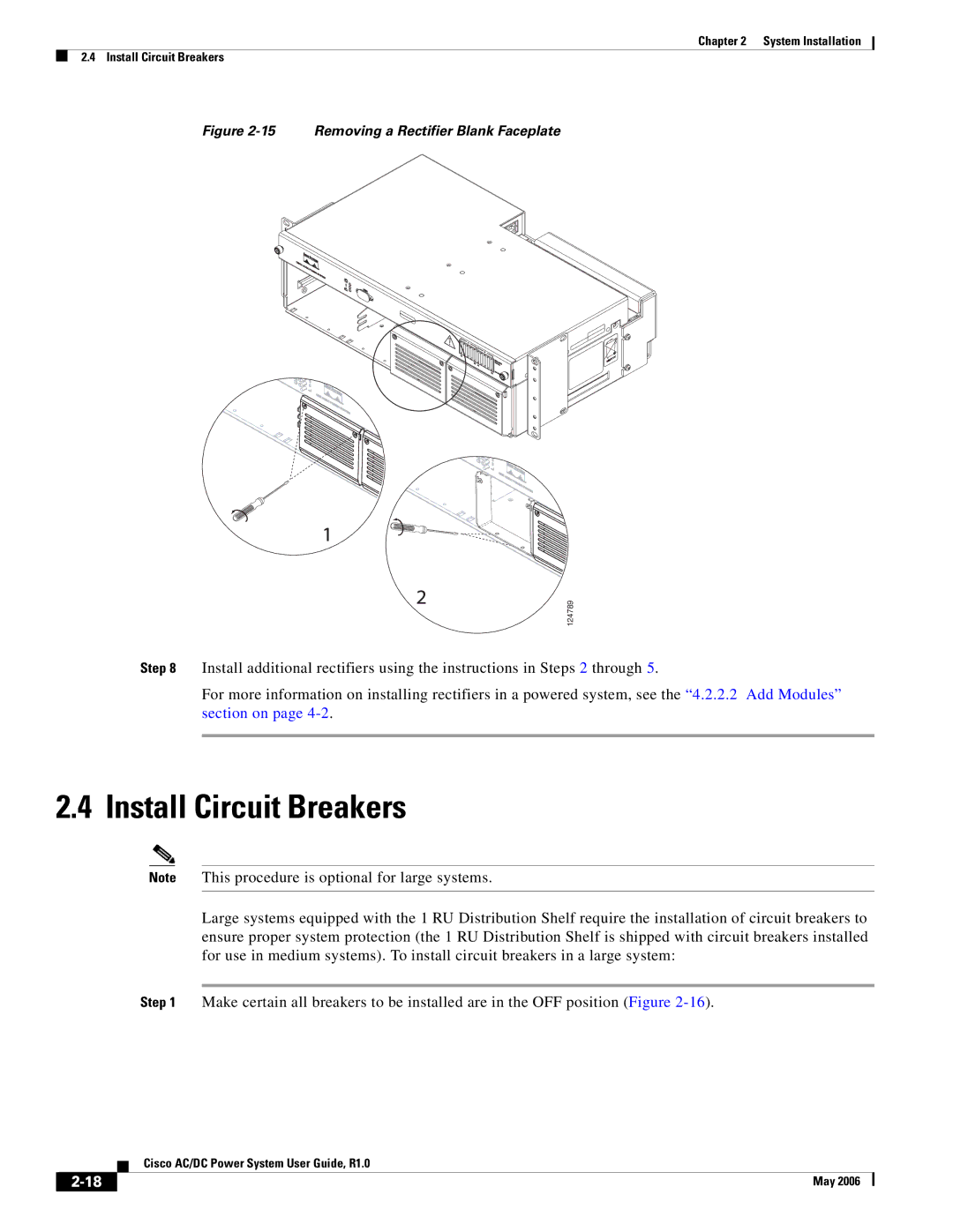
2-18
Common Not Used Normally Closed Hood
2-19
Figure 2-16 Circuit Breaker On/Off Positions
On Off
System Size
2-20
Figure 2-18 Installing a Circuit Breaker
Table 2-5 Circuit Breaker Positions
2.4.1 Install the Alarm Cable
2-21
Cisco AC/DC Power System User Guide, R1.0
2-22
Chapter 2 System Installation 2.4.1 Install the Alarm Cable
Figure 2-19 Removing the Controller Faceplate
Service Loop Tie-off Points
2-23
Figure 2-20 Installing an Alarm Cable
Alarm and Jumper Designations
Wire Gauge Stranded
2.5 Install Load-and-Return Connections
2-24
Applications
2-25
2.5.1 Install GMT Fuse Connections
Table 2-7 Recommended Wire Sizes continued
Blank 15A Fuse Blank
2.5.2 Install 1 RU Distribution Shelf Load Connections
2-26
2-27
A2 A1 B1 B2 Return Load
Figure 2-25 Installing Load Connections
2.6.1 GMT Fuses
2.6 System Upgrades
2.6.2 Small to Medium System Upgrade
2-28
2.6.4 Small to Large System Upgrade
2.6.3 Medium to Large System Upgrade
2-29
Chapter 2 System Installation 2.6.4 Small to Large System Upgrade
2-30
Cisco AC/DC Power System User Guide, R1.0
3.2 Component Replacement
Component Replacement
3.1 Safety
3.2.1 Replace the 1 RU Distribution Shelf
Note Cover the connectors to insulate the live current on the lugs
3.2.2 Replace the Controller Tray
J16 terminal block
3 far right of J9
Wire to be on the
4 Wire to be on the
center pin of J8
3.2.3 Replace Circuit Breakers
Figure 3-6 Circuit Breaker On/Off Positions
Step 3 Locate the breaker that is to be removed
Chapter 3 Component Replacement 3.2.3 Replace Circuit Breakers
Cisco AC/DC Power System User Guide, R1.0
Figure 3-7 Removing the 1 RU Distribution Shelf Faceplate
3.2.4 Replace a Rectifier
Figure 3-9 Removing a Rectifier
3.2.5 Replace GMT Fuses
3-10
4.2 General Information
System Operation
4.1 System Commissioning
C H A P T E R
4.2.2.1 Start the Controller
4.2.1 Alarm Interface Board and Connections
4.2.2 Basic Controller Functions
4.2.2.2 Add Modules
4.2.2.3 Remove Modules
Cisco AC/DC Power System User Guide, R1.0
Chapter 4 System Operation 4.2.2 Basic Controller Functions
System Troubleshooting
C H A P T E R
1. Tripped breaker 2. Fuse blown
Explanation More than one rectifier is reporting a module failure
Chapter 5 System Troubleshooting
Cisco AC/DC Power System User Guide, R1.0
System Parts List
C H A P T E R
Chapter 6 System Parts List Cisco AC/DC Power System User Guide, R1.0
Statement 12-Power Supply Disconnection Warning
Translated Safety Warnings
A P P E N D I X A
Page
Statement 43-Jewelry Removal Warning
Statement 1006-Chassis Warning for Rack-Mounting and Servicing
Page
Page
Page
Appendix A Translated Safety Warnings
Cisco AC/DC Power System User Guide, R1.0
Statement 1017-Restricted Area
A-10
Statement 1024-Ground Conductor
A-11
A-12
Statement 1030-Equipment Installation
A-13
Statement 1033-SELV-IEC 60950 DC Power Supply
A-14
Statement 1047-Overheating Prevention
A-15
A-16
Statement 1074-Comply with Local and National Electrical Codes
A-17
Appendix A Translated Safety Warnings
A-18
Cisco AC/DC Power System User Guide, R1.0