Chapter 2 System Installation
2.2.2 Install the 1 RU Distribution Shelf
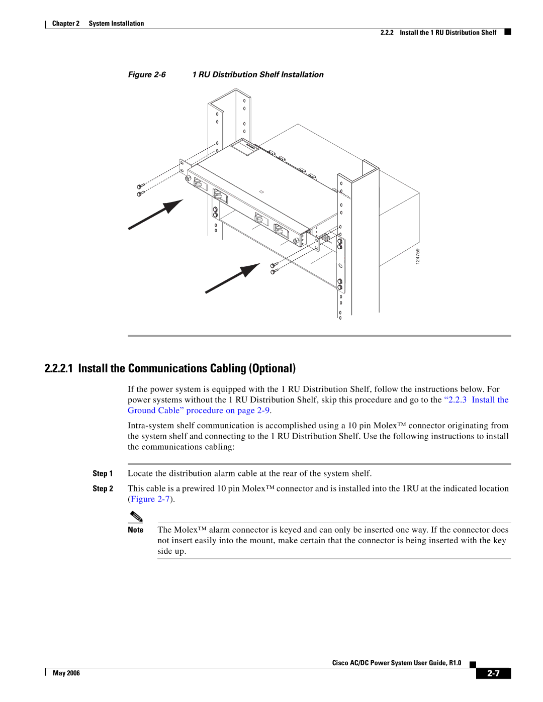
Figure 2-6 1 RU Distribution Shelf Installation
124759
2.2.2.1 Install the Communications Cabling (Optional)
If the power system is equipped with the 1 RU Distribution Shelf, follow the instructions below. For power systems without the 1 RU Distribution Shelf, skip this procedure and go to the “2.2.3 Install the Ground Cable” procedure on page
Step 1 Locate the distribution alarm cable at the rear of the system shelf.
Step 2 This cable is a prewired 10 pin Molex™ connector and is installed into the 1RU at the indicated location (Figure
Note The Molex™ alarm connector is keyed and can only be inserted one way. If the connector does not insert easily into the mount, make certain that the connector is being inserted with the key side up.
Cisco AC/DC Power System User Guide, R1.0
| May 2006 |
| |
|
|