Figures
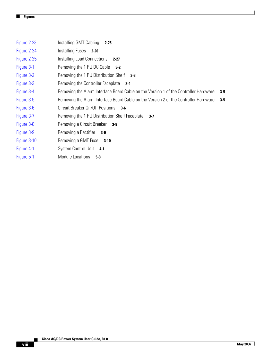
Figure | Installing GMT Cabling |
|
|
| ||
Figure | Installing Fuses |
|
|
|
| |
Figure | Installing Load Connections |
|
| |||
Figure | Removing the 1 RU DC Cable |
|
| |||
Figure | Removing the 1 RU Distribution Shelf |
| ||||
Figure | Removing the Controller Faceplate |
| ||||
Figure | Removing the Alarm Interface Board Cable on the Version 1 of the Controller Hardware | |||||
Figure | Removing the Alarm Interface Board Cable on the Version 2 of the Controller Hardware | |||||
Figure | Circuit Breaker On/Off Positions |
| ||||
Figure | Removing the 1 RU Distribution Shelf Faceplate |
| ||||
Figure | Removing a Circuit Breaker |
|
| |||
Figure | Removing a Rectifier |
|
|
| ||
Figure | Removing a GMT Fuse |
|
|
| ||
Figure | System Control Unit |
|
|
| ||
Figure | Module Locations |
|
|
| ||
Cisco AC/DC Power System User Guide, R1.0
| viii | May 2006 |
|
|
|
