Chapter 2 System Installation
2.4 Install Circuit Breakers
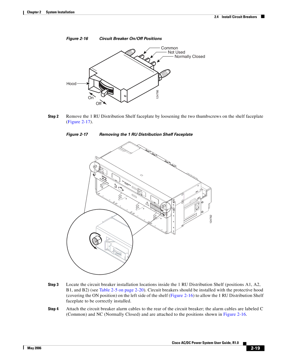
Figure 2-16 Circuit Breaker On/Off Positions
Common
Not Used
![]() Normally Closed
Normally Closed
Hood
On
Off ![]()
124766
Step 2 Remove the 1 RU Distribution Shelf faceplate by loosening the two thumbscrews on the shelf faceplate (Figure
Figure 2-17 Removing the 1 RU Distribution Shelf Faceplate
124762
Step 3 Locate the circuit breaker installation locations inside the 1 RU Distribution Shelf (positions A1, A2, B1, and B2) (see Table
Step 4 Attach the circuit breaker alarm cables to the rear of the circuit breaker; the alarm cables are labeled C (Common) and NC (Normally Closed) and are attached to the positions shown in Figure
Cisco AC/DC Power System User Guide, R1.0
| May 2006 |
| |
|
|