Cisco Systems 159330, 124792, 124778 manual J16 terminal block

Models: 159330 124778 124792

1 96
Download 96 pages 5.18 Kb
Page 62
Image 62
•–J16 terminal block

Chapter 3 Component Replacement

3.2.2 Replace the Controller Tray

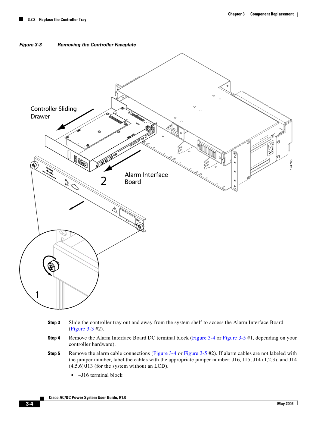
Figure 3-3 Removing the Controller Faceplate

124765

Step 3 Slide the controller tray out and away from the system shelf to access the Alarm Interface Board (Figure 3-3#2).

Step 4 Remove the Alarm Interface Board DC terminal block (Figure 3-4or Figure 3-5#1, depending on your controller hardware).

Step 5 Remove the alarm cable connections (Figure 3-4or Figure 3-5#2). If alarm cables are not labeled with the jumper number, label the cables with the appropriate jumper number: J16, J15, J14 (1,2,3), and J14 (4,5,6)/J13 (for the system without an LCD).

–J16 terminal block

Cisco AC/DC Power System User Guide, R1.0

3-4

May 2006


Page 62
Image 62
Cisco Systems 159330, 124792, 124778 manual J16 terminal block