Chapter 2 System Installation
2.3.1 Install the Rectifiers
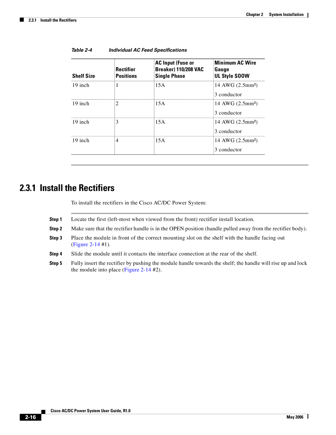
Table | Individual AC Feed Specifications |
|
| ||
|
|
|
|
|
|
|
|
| AC Input (Fuse or | Minimum AC Wire | |
|
| Rectifier | Breaker) 110/208 VAC | Gauge | |
Shelf Size |
| Positions | Single Phase | UL Style SOOW | |
|
|
|
|
|
|
19 inch |
| 1 | 15A | 14 AWG (2.5mm²) | |
|
|
|
| 3 conductor | |
|
|
|
|
|
|
19 inch |
| 2 | 15A | 14 AWG (2.5mm²) | |
|
|
|
| 3 conductor | |
|
|
|
|
|
|
19 inch |
| 3 | 15A | 14 AWG (2.5mm²) | |
|
|
|
| 3 conductor | |
|
|
|
|
|
|
19 inch |
| 4 | 15A | 14 AWG (2.5mm²) | |
|
|
|
| 3 conductor | |
|
|
|
|
|
|
|
|
|
|
|
|
2.3.1 Install the Rectifiers
To install the rectifiers in the Cisco AC/DC Power System:
Step 1 Locate the first
Step 2 Make sure that the rectifier handle is in the OPEN position (handle pulled away from the rectifier body).
Step 3 Place the module in front of the correct mounting slot on the shelf with the handle facing out (Figure
Step 4 Slide the module until it contacts the interface connection at the rear of the shelf.
Step 5 Fully insert the rectifier by pushing the module handle towards the shelf; the handle will rise up and lock the module into place (Figure
Cisco AC/DC Power System User Guide, R1.0
May 2006 |