I
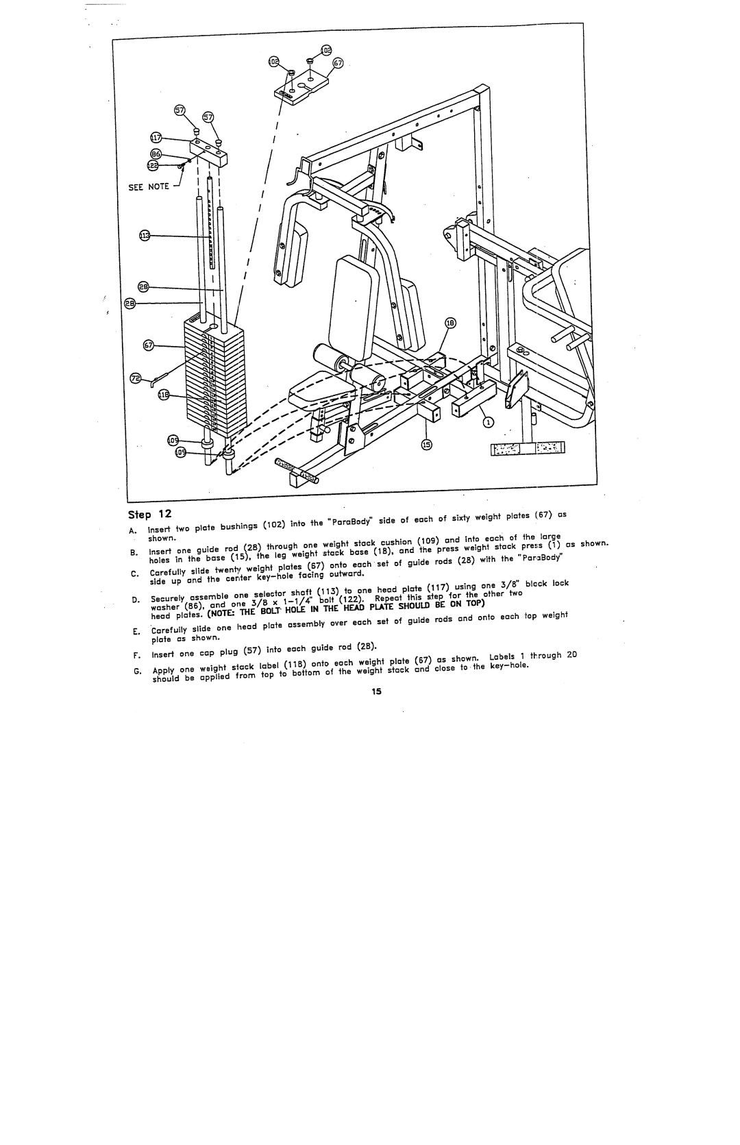
Step 12
A.
Insert two plate bushings ~102~ nto She °'ParaBody" side of each of sixty weight plates (677 as
shown.
B. Insert one guide rod (28~ through one weight stock cushion (109~ and into each of the large
hales in the base C15), the leg welghf stock base ~IB~, and the press weight stack press (1~ as shown.
C.
Ccrefully slide twen~ weight plates C67) onto eachset of guide rods (28~ with the "Pcr,=Body" side up and the cer=ter
Securely | assemble one selector | shaft | (113~ to | one head plcte | Cl17~ using | one 3/8" black look |
D. | I~ x | Repeat this | s,~ep for the | other two |
'Carefully slide one head plate assembly over each set of guide rods and onto each top weight
E.
plate as shown.
F.Insert one cap plug ~57~ into each guide rod (2B~.
G.
Apply one weight s~ack label (11B~ onto each weight plate ~67~ as shown. Labels 1 through 2.0 should be applied from top to bottom of the weight stack and close to ,the
15
