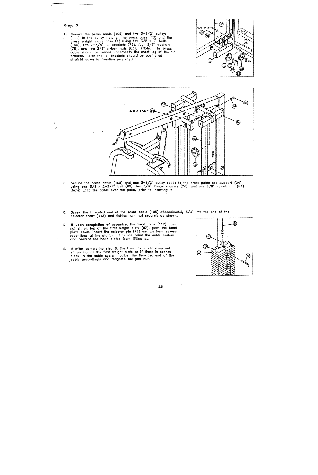
Ao Secure the press cable (105) and two
(111)~o the pu!ley flats on the press base (13) and ~ress weight slack base (1) using two 3//8 x 2" bolts
(78), and two 3/8" nylock nuts (83). (Note: The
cable should be routed underneath the shaft leg of the 'L' bracket. Also the 'L' brackets should be positioned s~ra~ghf downto function properly.)
Secure the press cable (105) and one
u~ingone3/s x
(Note: Loop the cable over the pulley prior .~o inserting if
C.Screw the threaded end of the press cable (105) approxlmately 3/4" into the end of the selector shaft (113) and tighten }am nut securely as shown.
D.If upon completion of assembly, the head plate (117) does
not sit on top of the first weight plate (67), push the head plate down, insert the selector pin (72) and perform several repetitions at the station. This will relax the cable system and prevent the hec=d plated from lifting up.
srt on top of the first weight plate or if there is excess
cable accordingly 0~nd retighten the jam nut.