4.3.2 Connecting to a DC Power Source
The 48 VDC power supply option uses a
WARNING! There are no
25
5.0 OPERATION
Once the Model 1092 is properly configured and installed, it should operate transparently. This sections describes
5.1 POWER-UP
To apply power to the Model 1092, first be sure that you have read Section 4.3, and that the unit is connected to the appropriate power source. Then
5.2 LED STATUS MONITORS
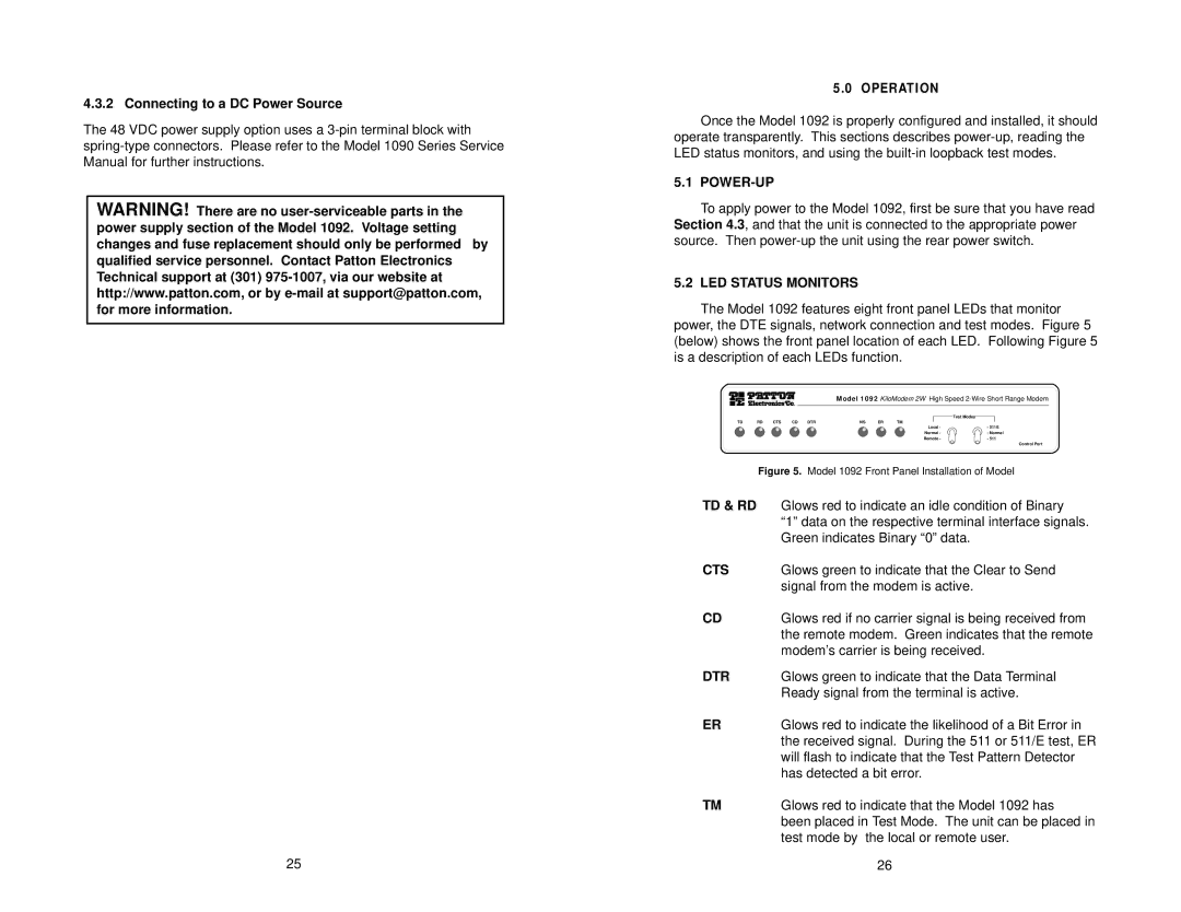
The Model 1092 features eight front panel LEDs that monitor power, the DTE signals, network connection and test modes. Figure 5 (below) shows the front panel location of each LED. Following Figure 5 is a description of each LEDs function.
Model 1092 KiloModem 2W High Speed
|
|
|
|
|
|
|
| Test Modes |
TD | RD | CTS | CD | DTR | NS | ER | TM |
|
|
|
|
|
|
|
| Local - | - 511E |
|
|
|
|
|
|
| Normal - | - Normal |
|
|
|
|
|
|
| Remote - | - 511 |
Control Port
Figure 5. Model 1092 Front Panel Installation of Model
TD & RD | Glows red to indicate an idle condition of Binary |
| “1” data on the respective terminal interface signals. |
| Green indicates Binary “0” data. |
CTS | Glows green to indicate that the Clear to Send |
| signal from the modem is active. |
CD | Glows red if no carrier signal is being received from |
| the remote modem. Green indicates that the remote |
| modem’s carrier is being received. |
DTR | Glows green to indicate that the Data Terminal |
| Ready signal from the terminal is active. |
ER | Glows red to indicate the likelihood of a Bit Error in |
| the received signal. During the 511 or 511/E test, ER |
| will flash to indicate that the Test Pattern Detector |
| has detected a bit error. |
TM | Glows red to indicate that the Model 1092 has |
| been placed in Test Mode. The unit can be placed in |
| test mode by the local or remote user. |
| 26 |