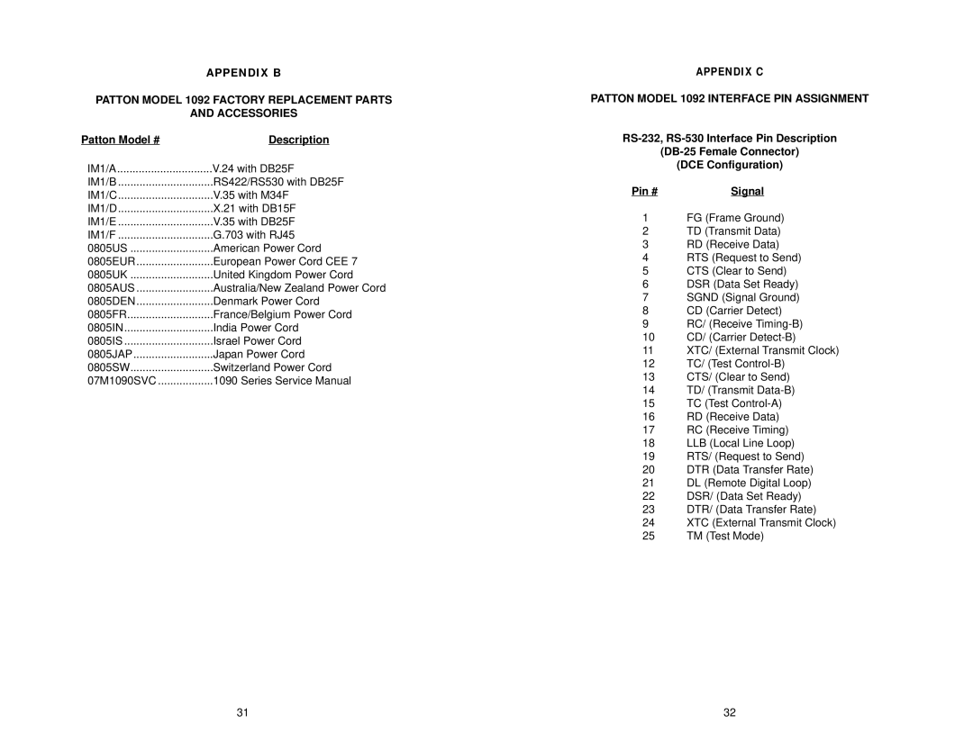
APPENDIX B
PATTON MODEL 1092 FACTORY REPLACEMENT PARTS
AND ACCESSORIES
Patton Model # | Description |
IM1/A | V.24 with DB25F |
IM1/B | RS422/RS530 with DB25F |
IM1/C | V.35 with M34F |
IM1/D | X.21 with DB15F |
IM1/E | V.35 with DB25F |
IM1/F | G.703 with RJ45 |
0805US | American Power Cord |
0805EUR | European Power Cord CEE 7 |
0805UK | United Kingdom Power Cord |
0805AUS | Australia/New Zealand Power Cord |
0805DEN | Denmark Power Cord |
0805FR | France/Belgium Power Cord |
0805IN | India Power Cord |
0805IS | Israel Power Cord |
0805JAP | Japan Power Cord |
0805SW | Switzerland Power Cord |
07M1090SVC | 1090 Series Service Manual |
APPENDIX C
PATTON MODEL 1092 INTERFACE PIN ASSIGNMENT
(DCE Configuration)
Pin # | Signal |
1FG (Frame Ground)
2TD (Transmit Data)
3RD (Receive Data)
4RTS (Request to Send)
5CTS (Clear to Send)
6DSR (Data Set Ready)
7SGND (Signal Ground)
8CD (Carrier Detect)
9RC/ (Receive
10CD/ (Carrier
11XTC/ (External Transmit Clock)
12TC/ (Test
13CTS/ (Clear to Send)
14TD/ (Transmit
15TC (Test
16RD (Receive Data)
17RC (Receive Timing)
18LLB (Local Line Loop)
19RTS/ (Request to Send)
20DTR (Data Transfer Rate)
21DL (Remote Digital Loop)
22DSR/ (Data Set Ready)
23DTR/ (Data Transfer Rate)
24XTC (External Transmit Clock)
25TM (Test Mode)
31 | 32 |