PATTON ELECTRONICS CO. | 3040/V35 | INSTALLATION AND OPERATIONS MANUAL |
139001UA
Tail Circuit Buffers (SW16-4)
The 3040/V35 (CTS MD-V.35/TCB) has a Tail Circuit Buffer that is automatically selected when a Sub-Channel is set as a DTE. The buffer will provide clock synchronization of the data from the Sub-Channel to the Master Port for Tail Circuit operations. The buffer is de-activated when the Sub-Channel is configured as a DCE. When operating in an asynchronous environment the Buffer must be bypassed. To bypass the buffer in a synchronous or asynchronous application, set switch SW16-4 to OFF (ASYNC). For normal operation in a synchronous environment set SW16-4 to ON (SYNC). When using a tail circuit modem with the 3040/V35 (CTS MD-V.35/TCB), the modem connected to the Sub-Channel, should be set to External Transmit Clocking. The modem at the remote end of the connection should be set to RX-TX Clocking or Slaved TX Clock. This will insure the same clock is present throughout the network and clock slippage will not occur.
Port DCE/DTE Selection (SW5 thru SW14)
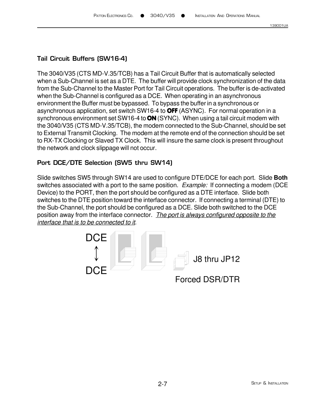
Slide switches SW5 through SW14 are used to configure DTE/DCE for each port. Slide Both switches associated with a port to the same position. Example: If connecting a modem (DCE Device) to the PORT, then the port should be configured as a DTE interface. Slide both switches to the DTE position toward the interface connector. If connecting a terminal (DTE) to the Sub-Channel, the port should be configured as a DCE. Slide both switched to the DCE position away from the interface connector. The port is always configured opposite to the interface that is to be connected to it.
DCE
DCE 
J8 thru JP12
Forced DSR/DTR