PATTON ELECTRONICS CO. | 3040/V35 | INSTALLATION AND OPERATIONS MANUAL |
139001UA
CHAPTER 1 - OPERATION
The Patton 3040/V35 (CTS MD-V.35/TCB) is a network enhancement accessory intended for high speed synchronous or asynchronous V.35 modem, DSU/CSU, or port sharing applications. The 3040/V35 (CTS MD-V.35/TCB) allows for immediate expansion of a system without the requirement of additional communication lines. The 3040/V35 (CTS MD- V.35/TCB) allows any combination of up to four V.35 DCE or DTE devices to share a single V.35 DCE or DTE high speed link in a point-to-point or multi-point polled network.
Channel Clocking
The 3040/V35 (CTS MD-V.35/TCB) is protocol transparent and operates in synchronous and asynchronous environments at data rates up to 2.048Mbps, depending on cable length and attached equipment. Clocking can be derived from the Master Port clock, (pins Y,AA for TT or U,W for ETT and V,X for RT), the internal clock generator or any Sub-Channel clock, (pins Y,AA for TT or U,W for ETT and V,X for RT).
Fallback Clocking
In the event of loss of an externally provided clock or optionally Sub-Channel 1 DCD becoming inactive, the 3040/V35 (CTS MD-V.35/TCB) has the ability to automatically fall back to the predetermined internal baud rate clock or the Sub-Channel 4 RX Clock (pins V,X).
Channel Interface
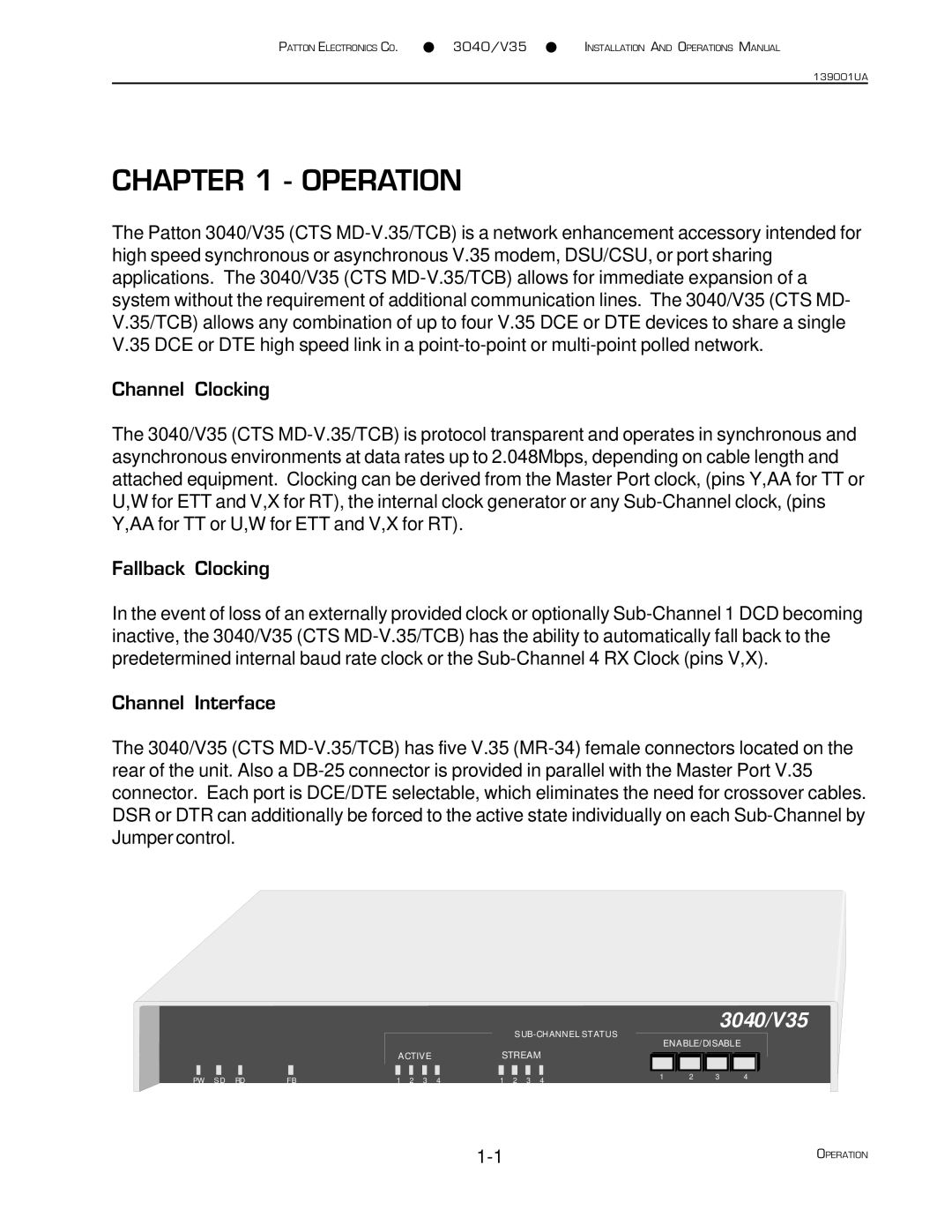
The 3040/V35 (CTS MD-V.35/TCB) has five V.35 (MR-34) female connectors located on the rear of the unit. Also a DB-25 connector is provided in parallel with the Master Port V.35 connector. Each port is DCE/DTE selectable, which eliminates the need for crossover cables. DSR or DTR can additionally be forced to the active state individually on each Sub-Channel by Jumper control.
SUB-CHANNEL STATUS
ACTIVESTREAM
PW S D RD | FB | 1 2 3 4 | 1 2 3 4 | 1 | 2 | 3 | 4 |

