SmartNode 5400 Getting Started Guide | 3 • SmartNode installation |
|
|
Connecting the power supply
The 5400 has the option of an internal or external Internal AC Power Supply, or an internal or external Verify that the green Power LED is lit (see figure 5)..
Internal AC Power Supply.
•Do not connect power to the AC Mains at this time.
• There are no
WARNING tion of the Model 5400. Contact Patton Electronics Technical support at
•The internal power supply automatically adjusts to accept an input voltage from 100 to 240 VAC (50/60 Hz).
Verify that the proper voltage is present before plugging the power cord into the receptacle. Failure to do so could result in equipment damage.
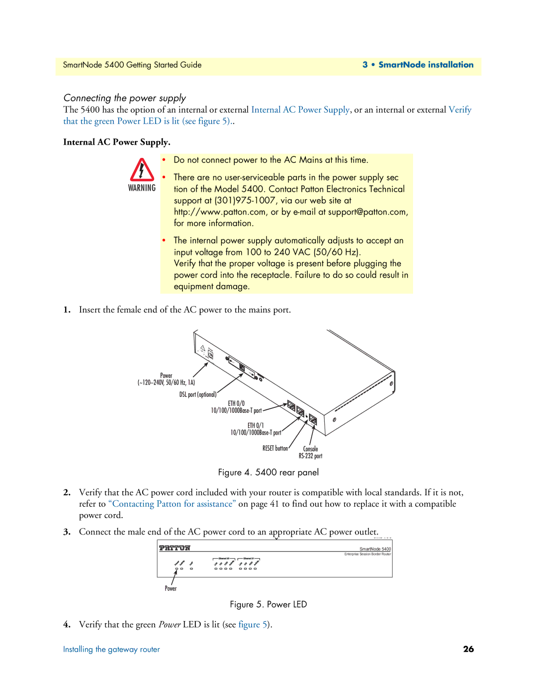
1.Insert the female end of the AC power to the mains port.
–
+
12V,1. | ACT |
25A |
|
Power | LI |
NK |
DSL port (optional)
ETH 0/0
ETH 0/1
Reset | Console |
| |
| RS- |
| 232 |
Console
Figure 4. 5400 rear panel
2.Verify that the AC power cord included with your router is compatible with local standards. If it is not, refer to “Contacting Patton for assistance” on page 41 to find out how to replace it with a compatible power cord.
3.Connect the male end of the AC power cord to an appropriate AC power outlet.
SmartNode 5400 |
Enterprise Session Border Router |
Power
Figure 5. Power LED
4.Verify that the green Power LED is lit (see figure 5).
Installing the gateway router | 26 |