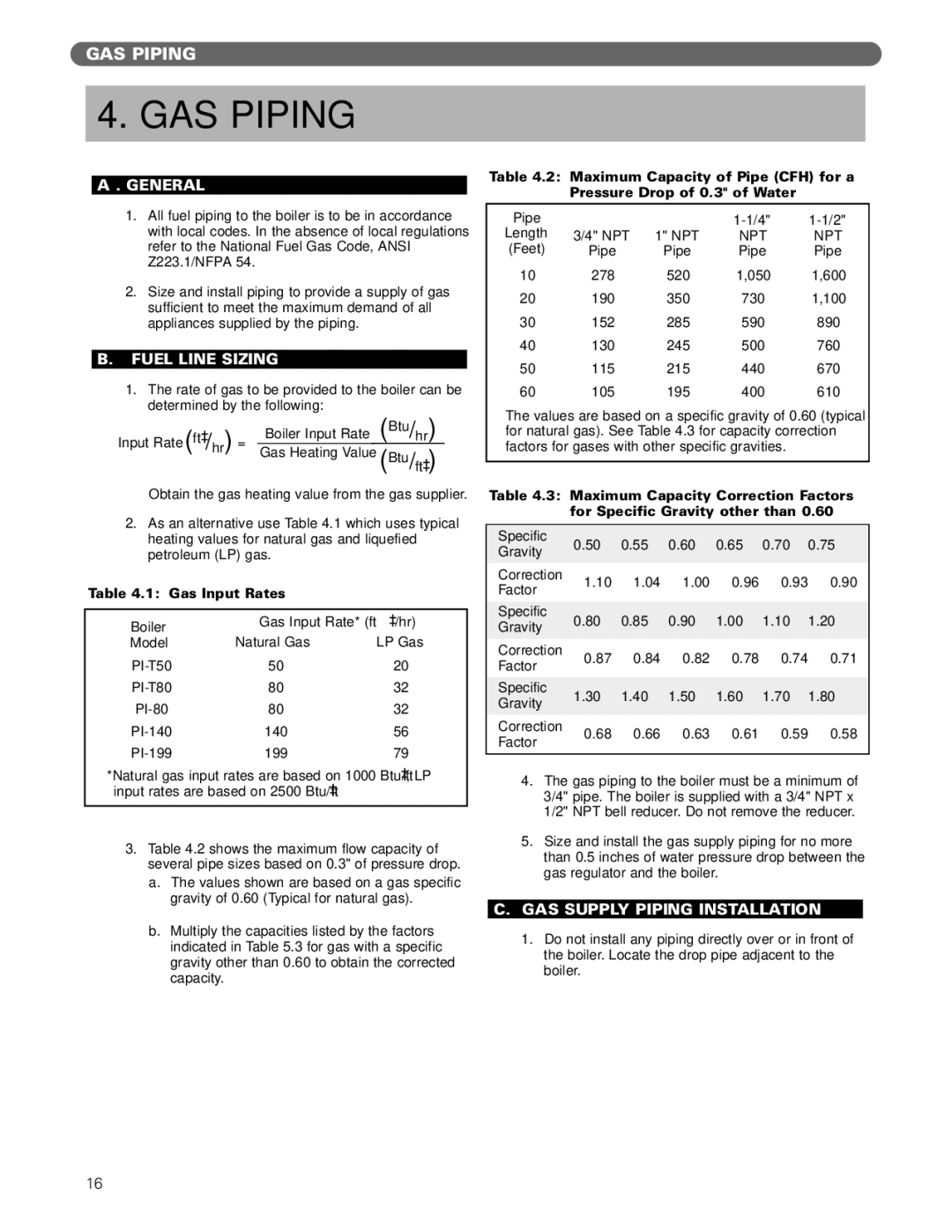
Gas Boiler specifications
PB Heat Gas Boilers are renowned for their efficiency, reliability, and advanced technology, making them a popular choice for residential heating needs. With a range of models available, these boilers cater to various heating requirements while maintaining high performance and energy efficiency.One of the standout features of PB Heat Gas Boilers is their exceptional efficiency ratings. Most models are designed to achieve AFUE (Annual Fuel Utilization Efficiency) ratings of over 90%, ensuring minimal energy waste and lower utility bills for homeowners. This high efficiency not only translates to cost savings but also contributes to a reduced carbon footprint, making PB Heat boilers a sustainable choice for environmentally conscious consumers.
PB Heat utilizes cutting-edge technologies to enhance the performance of their gas boilers. One such technology is the dual-stage gas valve, which allows for better modulation of gas flow, enabling the boiler to adapt to varying heating demands. This feature ensures consistent comfort while minimizing unnecessary energy consumption. Additionally, many PB Heat models come equipped with smart controls that can be easily integrated with home automation systems, giving homeowners the ability to monitor and adjust their heating remotely for maximum convenience and efficiency.
Durability and ease of maintenance are also key characteristics of PB Heat Gas Boilers. Constructed from high-quality materials, these boilers are designed to withstand the rigors of day-to-day operation. Features such as a corrosion-resistant heat exchanger contribute to the longevity of the unit, while easily accessible components simplify routine maintenance tasks, reducing downtime and service costs.
PB Heat Gas Boilers are available in various configurations, including wall-mounted and floor-standing models, catering to different space and installation requirements. This versatility allows homeowners to choose a solution that best fits their living environment while ensuring optimal heating performance.
In conclusion, PB Heat Gas Boilers represent a blend of advanced technology, energy efficiency, and robust construction. With their high efficiency ratings, smart control options, and durable design, these boilers provide reliable heating solutions for homes of all sizes. Choosing a PB Heat Gas Boiler means investing in a product that not only delivers comfort but also aligns with energy-saving and sustainability goals.

