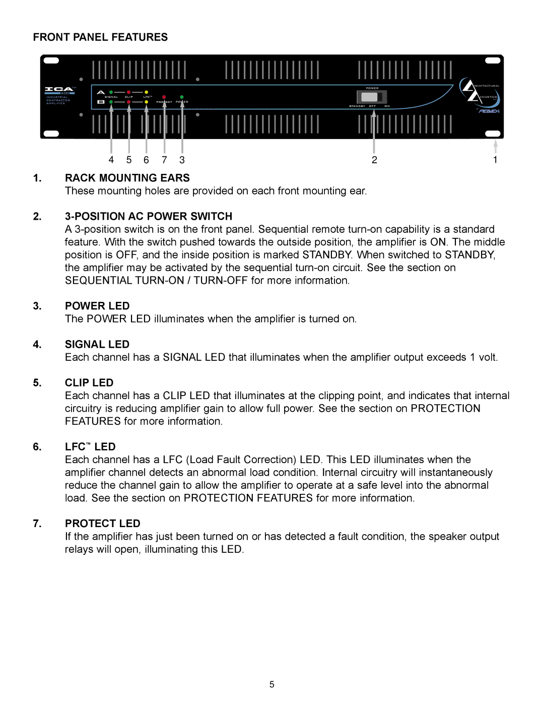
FRONT PANEL FEATURES
TM | RCHITECTURAL |
POWER |
|
|
|
| 600 |
|
| A |
|
|
|
|
|
|
|
|
|
|
|
|
|
|
|
|
|
|
|
|
|
|
|
|
|
|
|
|
|
|
|
|
|
|
|
|
|
|
|
|
|
|
|
|
|
|
|
|
|
| ||
|
|
|
|
|
|
|
| LFCTM |
|
|
|
|
|
|
|
|
|
|
|
|
|
|
|
|
|
|
|
|
|
|
|
|
|
|
|
|
|
|
|
|
|
|
| COUSTICS | |||||||||||||||
INDUSTRIAL |
|
| SIGNAL CLIP |
|
|
|
|
|
|
|
|
|
|
|
|
|
|
|
|
|
|
|
|
|
|
|
|
|
|
|
|
|
|
|
|
|
|
| |||||||||||||||||||||
CONTRACTOR |
| B |
|
|
|
|
|
|
|
| PROTECT POWER |
|
|
|
|
|
|
|
|
|
|
|
|
|
|
|
|
| TM | ||||||||||||||||||||||||||||||
AMPLIFIER |
|
|
|
|
|
|
|
|
|
|
|
|
|
|
|
|
|
|
|
|
|
|
|
|
|
|
|
|
| ||||||||||||||||||||||||||||||
|
|
|
|
|
|
|
|
|
|
|
|
|
|
|
|
|
|
|
|
|
|
|
|
|
|
|
|
|
| STANDBY OFF |
| ON | |||||||||||||||||||||||||||
|
|
|
|
|
|
|
|
|
|
|
|
|
|
|
|
|
|
|
|
|
|
|
|
|
|
|
|
|
|
|
|
|
|
|
|
|
|
|
|
|
|
|
|
|
|
|
|
|
|
|
|
|
|
| by | ||||
|
|
|
|
|
|
|
|
|
|
|
|
|
|
|
|
|
|
|
|
|
|
|
|
|
|
|
|
|
|
|
|
|
|
|
|
|
|
|
|
|
|
|
|
|
|
|
|
|
|
|
|
|
|
|
|
|
|
|
|
|
|
|
|
|
|
|
|
|
|
|
|
|
|
|
|
|
|
|
|
|
|
|
|
|
|
|
|
|
|
|
|
|
|
|
|
|
|
|
|
|
|
|
|
|
|
|
|
|
|
|
|
|
|
|
|
|
|
|
|
|
|
|
|
|
|
|
|
|
|
|
|
|
|
|
|
|
|
|
|
|
|
|
|
|
|
|
|
|
|
|
|
|
|
|
|
|
|
|
|
|
|
|
|
|
|
|
|
|
|
|
|
|
|
|
|
|
|
|
|
|
|
|
|
|
|
|
|
|
|
|
|
|
|
|
|
|
|
|
|
|
|
|
|
|
|
|
|
|
|
|
|
|
|
|
|
|
|
|
|
|
|
|
|
|
|
|
|
|
|
|
|
|
|
|
|
|
|
|
|
4 | 5 | 6 | 7 | 3 | 2 | 1 |
1.RACK MOUNTING EARS
These mounting holes are provided on each front mounting ear.
2.3-POSITION AC POWER SWITCH
A
3.POWER LED
The POWER LED illuminates when the amplifier is turned on.
4.SIGNAL LED
Each channel has a SIGNAL LED that illuminates when the amplifier output exceeds 1 volt.
5.CLIP LED
Each channel has a CLIP LED that illuminates at the clipping point, and indicates that internal circuitry is reducing amplifier gain to allow full power. See the section on PROTECTION FEATURES for more information.
6.LFC™ LED
Each channel has a LFC (Load Fault Correction) LED. This LED illuminates when the amplifier channel detects an abnormal load condition. Internal circuitry will instantaneously reduce the channel gain to allow the amplifier to operate at a safe level into the abnormal load. See the section on PROTECTION FEATURES for more information.
7.PROTECT LED
If the amplifier has just been turned on or has detected a fault condition, the speaker output relays will open, illuminating this LED.
5