FADE-IN PROTECTION
This feature operates every time the amplifier is turned on, or after a protect condition. During turn on, the amplifier goes into protect mode and leaves the speaker load disconnected until the amplifier determines that the operating status is normal. The
THERMAL PROTECTION
If the heatsink or power transformer reaches an abnormally high temperature, the amplifier will protect itself by disconnecting the speaker load until the amplifier returns to a normal temperature. During this time, the PROTECT LED will illuminate, and the cooling fan will operate at maximum speed.
SHORT CIRCUIT
If an output is shorted, the LFC™, speaker relay and thermal circuits will automatically protect the amplifier. The LFC circuit senses the short circuit as an abnormal load condition and reduces the channel gain to a safe level for the load. In extreme or severe conditions, the speaker relays will disconnect the load and initiate a
DC VOLTAGE PROTECTION
If an amplifier channel detects DC voltage or subsonic signals at its output terminals, the speaker relay will immediately open to prevent loudspeaker damage. The PROTECT LED will illuminate as notification of this condition.
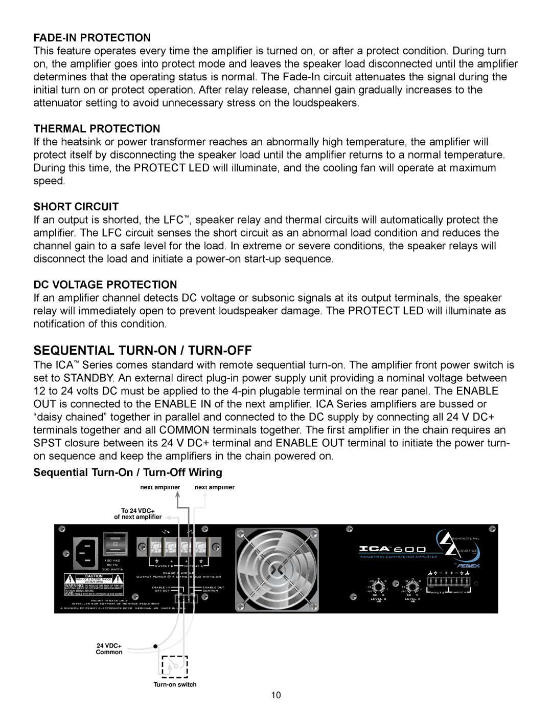
SEQUENTIAL TURN-ON / TURN-OFF
The ICA™ Series comes standard with remote sequential
Sequential Turn-On / Turn-Off Wiring
| To enable In of | To common of |
|
|
|
|
|
| next amplifier | next amplifier |
|
|
|
|
|
To 24 VDC+ |
|
|
|
|
|
| |
of next amplifier |
|
|
|
|
|
| |
|
|
|
|
|
|
| RCHITECTURAL |
|
|
|
| TM | 600 |
| |
|
|
|
|
| TM | ||
|
|
|
|
|
|
| COUSTICS |
|
|
| INDUSTRIAL CONTRACTOR AMPLIFIER |
| |||
120 VAC |
|
|
|
|
|
|
|
60 Hz | OUTPUT B | OUTPUT A |
|
|
|
| by |
|
|
|
|
| |||
700 WATTS |
|
|
|
|
|
|
|
CAUTION | CLASS 2 WIRING |
|
|
|
|
| |
OUTPUT POWER @ 4 OHMS IS 300 WATTS/CH |
|
|
| ||||
|
|
|
| ||||
|
|
|
| ||||
WARNING: TO REDUCE THE RISK OF FIRE OR | ENABLE IN | ENABLE OUT |
|
|
| ||
ELECTRIC SHOCK DO NOT EXPOSE THIS EQUIPMENT |
| ||||||
TO RAIN OR MOISTURE. | 24V DC+ | COMMON |
| ||||
| INPUT B | INPUT A | |||||
AVIS: RISQUE DE CHOC |
|
|
|
|
| ||
|
| 0 | 0 |
| |||
MOUNT IN RACK ONLY |
|
| LEVEL B | LEVEL A |
| ||
|
| (dB) |
| (dB) |
|
| |
INSTALLER SUR SUPPORT DE MONTAGE SEULEMENT |
|
|
|
|
|
| |
A DIVISION OF PEAVEY ELECTRONICS CORP. MERIDIAN, MS MADE IN U.S.A.
Sequential Turn On/
24 VDC+ Common
10