|
|
|
| Channel Functions |
| |
|
|
|
| |||
1 |
|
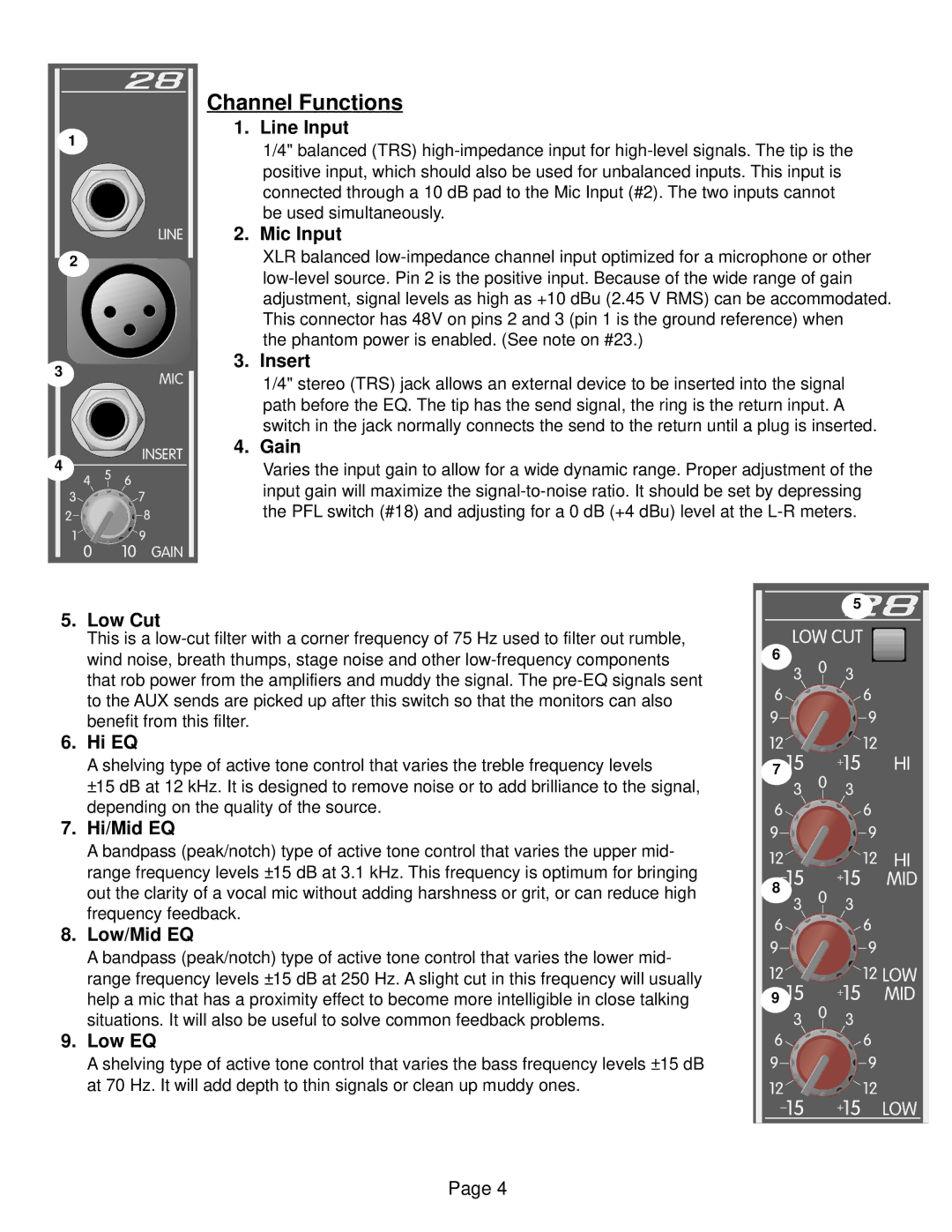
| 1. | Line Input | ||
|
|
|
| 1/4" balanced (TRS) | ||
|
|
|
|
| ||
|
|
|
|
| positive input, which should also be used for unbalanced inputs. This input is | |
|
|
|
|
| connected through a 10 dB pad to the Mic Input (#2). The two inputs cannot | |
|
|
|
|
| be used simultaneously. | |
|
|
| 2. | Mic Input | ||
2 |
|
|
|
| XLR balanced | |
|
|
| ||||
|
|
|
|
| ||
|
|
|
|
| adjustment, signal levels as high as +10 dBu (2.45 V RMS) can be accommodated. | |
|
|
|
|
| This connector has 48V on pins 2 and 3 (pin 1 is the ground reference) when | |
|
|
|
|
| the phantom power is enabled. (See note on #23.) | |
3
3. Insert
1/4" stereo (TRS) jack allows an external device to be inserted into the signal path before the EQ. The tip has the send signal, the ring is the return input. A switch in the jack normally connects the send to the return until a plug is inserted.
4. | Gain | |||||||
4 |
|
|
|
|
|
|
| Varies the input gain to allow for a wide dynamic range. Proper adjustment of the |
|
|
|
|
|
|
| ||
|
|
|
|
|
|
|
| input gain will maximize the |
|
|
|
|
|
|
|
| |
|
|
|
|
|
|
|
| the PFL switch (#18) and adjusting for a 0 dB (+4 dBu) level at the |
|
|
|
|
|
|
|
| |
5. Low Cut
This is a
that rob power from the amplifiers and muddy the signal. The
6. Hi EQ
A shelving type of active tone control that varies the treble frequency levels
±15 dB at 12 kHz. It is designed to remove noise or to add brilliance to the signal, depending on the quality of the source.
7.Hi/Mid EQ
A bandpass (peak/notch) type of active tone control that varies the upper mid-
range frequency levels ±15 dB at 3.1 kHz. This frequency is optimum for bringing out the clarity of a vocal mic without adding harshness or grit, or can reduce high frequency feedback.
8.Low/Mid EQ
A bandpass (peak/notch) type of active tone control that varies the lower mid-
range frequency levels ±15 dB at 250 Hz. A slight cut in this frequency will usually help a mic that has a proximity effect to become more intelligible in close talking situations. It will also be useful to solve common feedback problems.
9. Low EQ
A shelving type of active tone control that varies the bass frequency levels ±15 dB at 70 Hz. It will add depth to thin signals or clean up muddy ones.
5
6
7 ![]()
![]()
8
9![]()
![]()
Page 4