![]() 10
10
![]() 11
11
![]()
![]() 12
12
![]()
![]() 13
13
17
16 | 18 |
| |||||
| |||||||
|
|
|
|
|
|
|
|
|
|
|
|
|
|
|
|
|
|
|
|
|
|
|
|
|
|
|
|
|
|
|
|
|
|
|
|
|
|
|
|
|
|
|
|
|
|
|
|
|
|
|
|
|
|
|
|
|
|
|
|
|
|
|
|
|
|
|
|
|
|
|
|
|
|
|
|
|
|
|
|
|
|
|
|
|
|
|
|
20![]()
![]()
![]()
![]()
19 ![]()
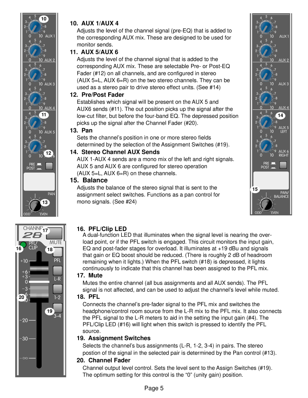
10. AUX 1/AUX 4
Adjusts the level of the channel signal
11. AUX 5/AUX 6
Adjusts the level of the channel signal that is added to the corresponding AUX mix. These are selectable Pre- or
(AUX 5=L, AUX 6=R) on the two stereo channels. They can be used as a stereo pair to drive stereo effect units. (See #14)
12. Pre/Post Fader
Establishes which signal will be present on the AUX 5 and
AUX6 sends (#11). The out position picks up the signal after the
13. Pan
Sets the channel’s position in one or more stereo fields
determined by the selection of the Assignment Switches (#19).
14. Stereo Channel AUX Sends
AUX
(AUX 5=L, AUX 6=R) on these channels.
15. Balance
Adjusts the balance of the stereo signal that is sent to the assignment select switches. Functions as a pan control for mono signals. (See #24)
16. PFL/Clip LED
A
17. Mute
Mutes the entire channel (all bus assignments and all AUX sends). The PFL signal is not affected, and can be used to adjust the channel’s level while muted.
18. PFL
Connects the channel’s
19. Assignment Switches
Selects the channel’s bus assignments
20. Channel Fader
Channel output level control. Sets the level sent to the Assign Switches (#19). The optimum setting for this control is the “0” (unity gain) position.
14
15
Page 5