CENTURY SERIES | SP / TC / GT |
Power Connections
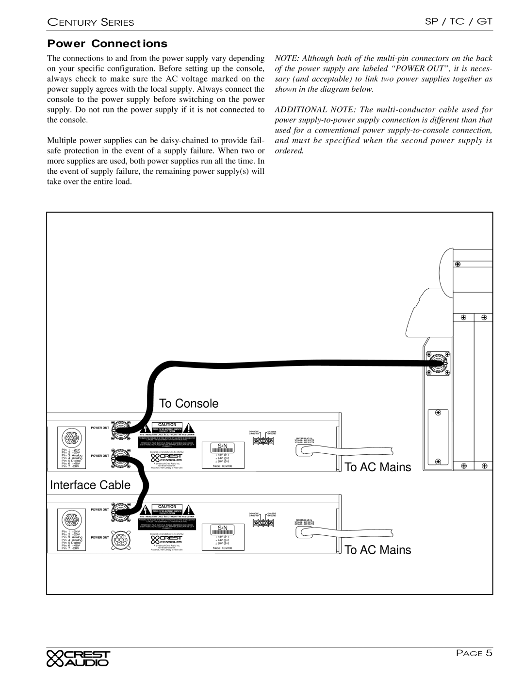
The connections to and from the power supply vary depending on your specific configuration. Before setting up the console, always check to make sure the AC voltage marked on the power supply agrees with the local supply. Always connect the console to the power supply before switching on the power supply. Do not run the power supply if it is not connected to the console.
Multiple power supplies can be
NOTE: Although both of the
ADDITIONAL NOTE: The
Ground Link
|
|
| To Console |
| |
|
| POWER OUT | CAUTION |
|
|
|
| RISK OF ELECTRIC SHOCK |
|
| |
2 1 |
| DO NOT OPEN | CONSOLE | CHASSIS | |
| AVIS : RISQUE DE CHOC | GROUND | GROUND | ||
|
|
| |||
5 4 3 |
| WARNING TO REDUCE THE RISK OF FIRE OR ELECTRIC SHOCK DO NOT |
| MAXIMUM AC IN: | |
7 | 6 |
| EXPOSE THIS EQUIPMENT TO RAIN OR MOISTURE. |
| XCVA04: 415 WATTS |
| ATTENTION! POUR ÉVITER LE RISQUE D'INCENDIE OU DE CHOC | Model XCVA04 | XCVA06: 825 WATTS | ||
|
|
| ÉLECTRIQUE, NE PLACEZ PAS CET APPAREIL SOUS LA PLUIE OU Á |
| |
|
|
| L'HUMIDITÉ | ± 20VS/N@ 4 |
|
Pin 1 +24V |
| Designed & manufactured in the USA by: | + 24V @ 4 |
| |
Pin 2 +20V |
|
| |||
Pin 3 | Analog | POWER OUT |
| + 48V @ 1 |
|
Pin 4 | Analog |
|
| + 24V @ 6 |
|
Pin 5 Digital |
|
| ± 20V @ 6 | To AC Mains | |
Pin 6 +48V |
| A division of Crest Audio Inc. | Model XCVA06 | ||
Pin 7 |
| 100 Eisenhower Dr. |
| ||
|
|
| Paramus, New Jersey 07652 USA |
|
|
Interface Cable |
|
|
| ||
|
| POWER OUT | CAUTION |
|
|
|
| RISK OF ELECTRIC SHOCK |
|
| |
2 1 |
| DO NOT OPEN | CONSOLE | CHASSIS | |
| AVIS : RISQUE DE CHOC | G R O U N D | GROUND | ||
|
|
| |||
5 4 3 |
| WARNING TO REDUCE THE RISK OF FIRE OR ELECTRIC SHOCK DO NOT |
| MAXIMUM AC IN: | |
7 | 6 |
| EXPOSE THIS EQUIPMENT TO RAIN OR MOISTURE. |
| XCVA04: 415 WATTS |
| ATTENTION! POUR ÉVITER LE RISQUE D'INCENDIE OU DE CHOC | Model XCVA04 | XCVA06: 825 WATTS | ||
|
|
| ÉLECTRIQUE, NE PLACEZ PAS CET APPAREIL SOUS LA PLUIE OU Á |
| |
|
|
| L'HUMIDITÉ | ± 20VS/N@ 4 |
|
Pin 1 +24V |
| Designed & manufactured in the USA by: | + 24V @ 4 |
| |
Pin 2 +20V |
|
| |||
Pin 3 | Analog | POWER OUT |
| + 48V @ 1 |
|
Pin 4 | Analog |
|
| + 24V @ 6 |
|
Pin 5 Digital |
|
| ± 20V @ 6 | To AC Mains | |
Pin 6 +48V |
| A division of Crest Audio Inc. | Model XCVA06 | ||
Pin 7 |
| 100 Eisenhower Dr. | |||
|
|
| Paramus, New Jersey 07652 USA |
|
|
|
|
|
|
| PAGE 5 |