SP / TC / GT | CENTURY SERIES |
|
| LINE | |
|
| +48V | |
|
| PAD | |
| 20 |
| GAIN |
|
|
| 30 |
10 |
|
|
|
6 |
| 60 | |
|
| 80 | |
| - 0 + | HF | |
|
|
| |
8 |
|
| 8 |
16 | - 0 + | 16 | |
| HM | ||
|
|
| |
8 |
|
| 8 |
16 | - 0 + | 16 | |
| LM | ||
|
|
| |
8 |
|
| 8 |
16 | - 0 + | 16 | |
| LF | ||
|
|
| |
8 |
|
| 8 |
16 |
|
| 16 |
|
| EQ IN | |
4 | 5 | 6 | 1•3 |
3 |
|
| 7 |
2 |
|
| 8 |
1 |
|
| 9 |
0 | 10 |
| |
4 | 5 | 6 | 2•4 |
3 |
|
| 7 |
2 |
|
| 8 |
1 |
|
| 9 |
0 | 10 |
| |
|
| 3•4 | |
|
| POST | |
4 | 5 | 6 | 5 |
3 |
|
| 7 |
2 |
|
| 8 |
1 |
|
| 9 |
0 | 10 |
| |
4 | 5 | 6 | 6 |
3 |
|
| 7 |
2 |
|
| 8 |
1 |
|
| 9 |
0 | 10 |
| |
4 | 5 | 6 | 7 |
3 |
|
| 7 |
|
|
| 8 |
3
28
19
0 10
4 5 6 6
3 7
28
19
0 10
4 5 6 7
3 7
28
19
0 10
4 5 6 8
3 7
28
19
0 10
| PRE |
AUX SENDS | |
| PAN |
| MUTE |
| MONO |
| L - R |
| 1 - 2 |
| 3 - 4 |
| 5 - 6 |
| 7 - 8 |
1 | PFL |
PEAK |
|
SIG |
|
0
5
10
20
30
40
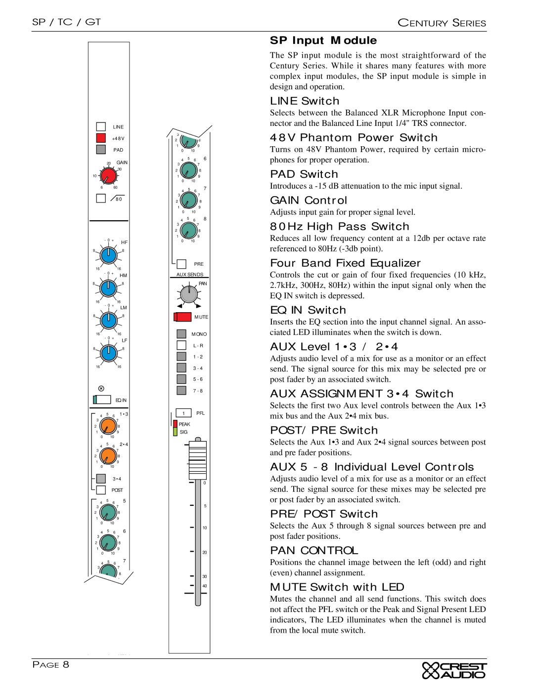
SP Input Module
The SP input module is the most straightforward of the Century Series. While it shares many features with more complex input modules, the SP input module is simple in design and operation.
LINE Switch
Selects between the Balanced XLR Microphone Input con- nector and the Balanced Line Input 1/4" TRS connector.
48V Phantom Power Switch
Turns on 48V Phantom Power, required by certain micro- phones for proper operation.
PAD Switch
Introduces a
GAIN Control
Adjusts input gain for proper signal level.
80Hz High Pass Switch
Reduces all low frequency content at a 12db per octave rate referenced to 80Hz
Four Band Fixed Equalizer
Controls the cut or gain of four fixed frequencies (10 kHz, 2.7kHz, 300Hz, 80Hz) within the input signal only when the EQ IN switch is depressed.
EQ IN Switch
Inserts the EQ section into the input channel signal. An asso- ciated LED illuminates when the switch is down.
AUX Level 1•3 / 2•4
Adjusts audio level of a mix for use as a monitor or an effect send. The signal source for this mix may be selected pre or post fader by an associated switch.
AUX ASSIGNMENT 3•4 Switch
Selects the first two Aux level controls between the Aux 1•3 mix bus and the Aux 2•4 mix bus.
POST/PRE Switch
Selects the Aux 1•3 and Aux 2•4 signal sources between post and pre fader positions.
AUX 5 - 8 Individual Level Controls
Adjusts audio level of a mix for use as a monitor or an effect send. The signal source for these mixes may be selected pre or post fader by an associated switch.
PRE/POST Switch
Selects the Aux 5 through 8 signal sources between pre and post fader positions.
PAN CONTROL
Positions the channel image between the left (odd) and right (even) channel assignment.
MUTE Switch with LED
Mutes the channel and all send functions. This switch does not affect the PFL switch or the Peak and Signal Present LED indicators, The LED illuminates when the channel is muted from the local mute switch.
PAGE 8