|
| CONNECTOR | |
HTR/FAN | VIDEO | FOR OPTIONAL | |
TRANSLATOR | |||
|
SUBASSEMBLY | ||
CONTROL | ||
| ||
SIGNALS |
|
PWR IN
RX–
RX+
TX–
TX+
FUSE
24 VAC
MIDDLE
PIN IS
GND
DOME DRIVE CONNECTOR
FAN
NOTE: (Spectra II™
Only) Connect only a low voltage device to the relay output. Maximum current rating of the relay contacts is two amperes.
CAUTION:
(Spectra II™ Only) The maxi-
mum output of AUX 2 is 150 mA. If you connect a device that draws more current, you could destroy the output transistor. The output is in- tended to drive logic circuits or
CAUTION: Leave adequate slack in the wiring to permit
the door to open without pulling on the connectors.
POWER |
|
(24 VAC ONLY) | 1.6 A |
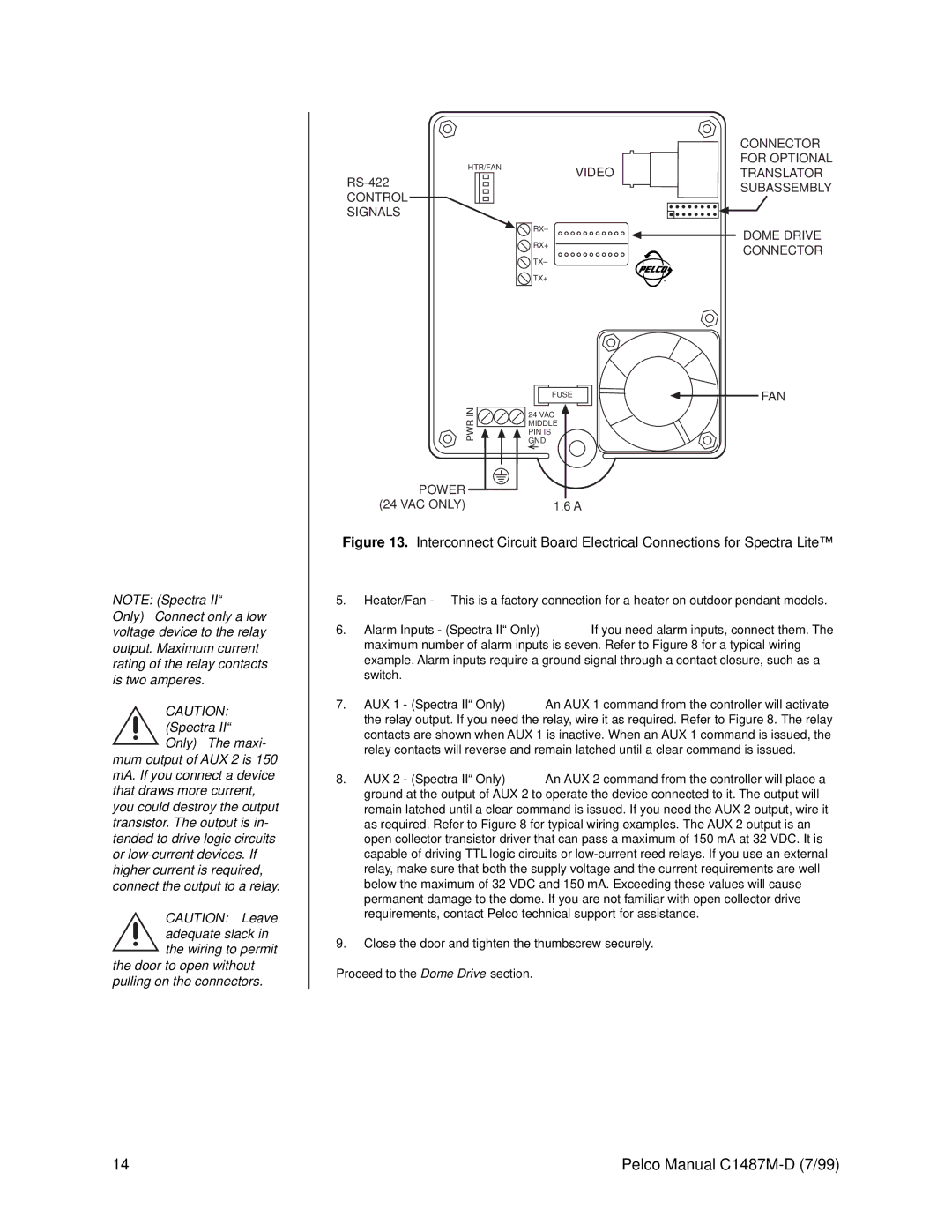
Figure 13. Interconnect Circuit Board Electrical Connections for Spectra Lite™
5.Heater/Fan - This is a factory connection for a heater on outdoor pendant models.
6.Alarm Inputs - (Spectra II™ Only) If you need alarm inputs, connect them. The maximum number of alarm inputs is seven. Refer to Figure 8 for a typical wiring example. Alarm inputs require a ground signal through a contact closure, such as a switch.
7.AUX 1 - (Spectra II™ Only) An AUX 1 command from the controller will activate the relay output. If you need the relay, wire it as required. Refer to Figure 8. The relay contacts are shown when AUX 1 is inactive. When an AUX 1 command is issued, the relay contacts will reverse and remain latched until a clear command is issued.
8.AUX 2 - (Spectra II™ Only) An AUX 2 command from the controller will place a ground at the output of AUX 2 to operate the device connected to it. The output will remain latched until a clear command is issued. If you need the AUX 2 output, wire it as required. Refer to Figure 8 for typical wiring examples. The AUX 2 output is an open collector transistor driver that can pass a maximum of 150 mA at 32 VDC. It is capable of driving TTL logic circuits or
9.Close the door and tighten the thumbscrew securely.
Proceed to the Dome Drive section.
14 | Pelco Manual |